Latest News & Releases
04
Jul
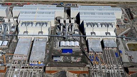


Important Milestone reached in the Fehmarnbelt Tunnel project: All five production lines for standard tunnel elements in operation
At the time of its completion, the 18 km long Fehmarnbelt Tunnel will be the longest immersed tunnel in the world and is currently the largest infrastructure project in Northern Europe. PERI developed a formwork solution for the production of the 79 standard tunnel elements, characterized by high performance, productivity and compliance with high safety standards. The standard tunnel elements are manufactured in parallel on five production lines, with the latest line having commenced operations in February 2024.
29
May
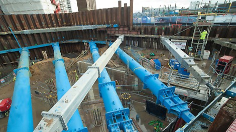
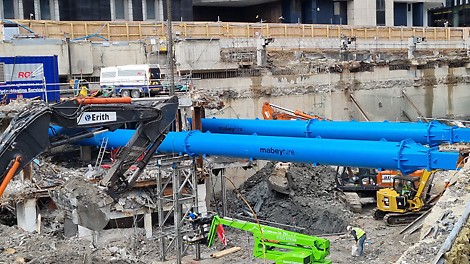

Mabey Hire Ltd. becomes part of the PERI Group
With effect from 21.05.2024, the PERI SE (Weissenhorn, Germany) has taken over Mabey Hire Ltd., headquartered in Dewsbury (UK).
17
Apr
Above water and clouds: Danjiang Bridge reaches record-breaking proportions with PERI Systems
The Danjiang Bridge over the Tamsui River on the outskirts of Taipei is taking giant strides towards record-breaking proportions. The structure, designed by Zaha Hadid, is expected to be the world’s longest asymmetric cable-stayed bridge upon completion in 2025, at an impressive 920.00 metres.
28
Mar
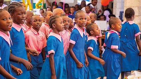


Opening of new school in Kenyan slum: The very first PERI school provides opportunities for the future
In Kenia wurde die erste Schule im Rahmen des PERI Nachhaltigkeitsprogramms feierlich eröffnet
The very first PERI school in Kenya opened its doors at the end of February 2024 for over 200 children. In Kibera, the largest slum in Nairobi, the first school in the PERI sustainability initiative “Building Sustainability” was built in less than a year. In collaboration with the social enterprise “Start Somewhere”, PERI developed what are known as TwistBlock Moulds for hollow concrete blocks, which were designed specifically for use in slums due to the simple and flexible manner in which they can be used. The new school building has created not only learning spaces, but also new local job opportunities.
20
Mar
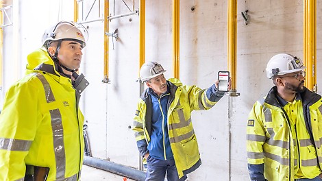

PERI is a member of buildingSMART International
• PERI SE is a member of buildingSMART International and in local chapter buildingSMART Deutschland • Common openBIM approach for formwork and scaffolding construction • Design and implementation of openBIM in the construction process
13
Feb
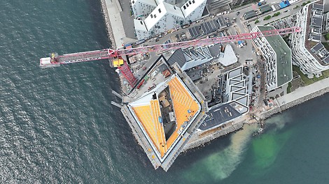


Award for Denmark’s tallest residential building
The “Lighthouse 2.0” construction project has created new living space with 381 new flats in the purpose-built district of “Aarhus Ø”, not far from the centre of the city of the same name. With its impressive height of 142 metres, the building has been the tallest residential building in Denmark since its completion in 2022. The top floors are home to a restaurant and a roof terrace that is open to the public – with fantastic views of the harbour, the sea and the city. The project has now received an award for the “Best Tall Building” in the “100 to 199 metres” category from non-profit organisation, the “Council on Tall Buildings and Urban Habitat” (CTBUH).
24
May
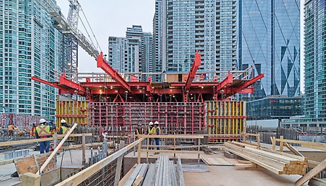


The Tallest Residential Tower in Canada is beginning to rise with PERI Climbing Systems
The Pinnacle One Yonge project is a multi-phase development, designed by Hariri Pontarini Architects. With its prominent location, across from Toronto’s harbour, the sleek, masterfully designed towers will reshape the city’s skyline. The first three phases of the One Yonge project include residential towers that are 65, 105 and 92 storeys tall respectively.
10
Aug
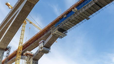


Building bridges with solution expertise and modular systems
Customer-oriented planning and services combined with coordinated modular systems form the basis for developing formwork and scaffolding solutions that are suitable for almost any site requirements, including complex infrastructure projects. Experienced PERI engineers assisted with the construction of the Filstal Bridge, bringing their extensive solution expertise to bear.
28
Jun
PERI at bauma: Innovative solutions for civil engineering
From 24 to 30 October 2022, the PERI exhibition hall at the northern open-air site (booth FN 719) in Munich will have the motto “Shaping the Future”. In addition to impressive exhibits, live demonstrations, personal discussions and information events, the formwork and scaffolding manufacturer will have many more surprises in store for visitors. Among other things, PERI will be showing innovations from the climbing formwork sector as well as further developments for civil engineering.
28
Jun
PERI shows the future of scaffolding at bauma
From 24 to 30 October 2022, the PERI exhibition hall at the northern open-air site (booth FN 719) in Munich will have the motto “Shaping the Future”. In addition to impressive exhibits, live demonstrations, personal discussions and information events, the scaffolding and formwork manufacturer will have many more surprises in store for visitors. Among other things, PERI will be showing completely new innovations for scaffolding as well as further developments of the digital planning tools.
02
Nov
PERI and STRABAG print first building in Austria
Austria’s first 3D-printed building is being constructed in Hausleiten, Lower Austria. Construction technology group STRABAG, together with PERI, the formwork and scaffolding manufacturer and a pioneer in 3D concrete printing, is realising a roughly 125 m² office building next to its asphalt mixing plant in Hausleiten. The pure printing time for the building extension is approx. 45 hours. The special dry mortar for the construction 3D printing project "Tector Print", with long workability and good pumpability, is being supplied by Lafarge.
28
Oct
Jürgen Voss appointed new Chief Financial Officer at PERI
Jürgen Voss will become Chief Financial Officer (CFO) of the PERI Group on 1 January 2022. He takes over this position from Christian Schwörer, who had held it on a transitional basis since 1 May 2021 in addition to his role as Chairman of the Executive Board (CEO).
07
Sep
Optimised concreting processes by measuring the concrete temperature and maturity with PERI sensors
With PERI InSite Construction, PERI is bringing various digital solutions to market that optimise the concreting process on the construction site and help to save time and cut costs. The key: a measuring device, a cloud and the sensors themselves. These include the PERI InSite Construction Temperature Monitoring and Concrete Maturity Kit for efficient measurement of the temperature and determination of the maturity of the concrete.
06
Aug
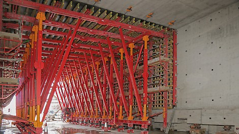


VARIOKIT VTC Tunnel Formwork Carriage supports construction of Werrington Grade Separation tunnel
For the construction of the Werrington Grade Separation tunnel, the VARIOKIT VTC Tunnel Formwork Carriage and other PERI standard components were used for a solution which, despite its rectangular structure, delivered a curved result. Optimally coordinated formwork and scaffolding solutions from a single source, as well as clever advance planning services, ensured that the project ran smoothly.
28
Jul
Germany´s first printed house officially openend
Germany's first printed house is ready for occupancy. Today, the single-family house printed by PERI using a COBOD BOD2 printer was officially opened in Beckum, North Rhine-Westphalia, by Ina Scharrenbach, Minister for Home, Municipal Affairs, Construction and Equality of the State of North Rhine-Westphalia. The state of North Rhine-Westphalia subsidized the project as part of its "Innovative Building" funding program.
25
May
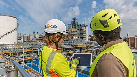


A modern approach to planning and work operations in industrial scaffolding construction
In the industrial environment more than anywhere else, process and operational reliability requirements are particularly stringent. At BASF SE in Ludwigshafen, Germany, PERI has demonstrated that safety and cost-effectiveness can be combined with ease by making use of state-of-the-art, BIM-based scaffold planning and innovative systems.
13
Apr
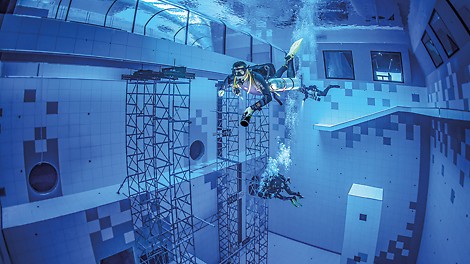


Diving in Poland: PERI constructs the deepest diving pool in the world
Far away from the world's well-known diving paradises, the Polish city of Mszczonów has become home to what is currently the deepest diving pool in the world. Numerous PERI systems were used for the construction of the pool, which has a depth of up to 45.50 metres. The special highlight was the dismantling of the ST 100 Stacking Towers used: for reasons relating to the static requirements, the stacking towers could only be dismantled after the pool had been filled with water – not by the company's own construction site staff, but by specially trained divers.
08
Mar
PERI is one of Germany's Top 100 Innovators
PERI, one of the world's leading manufacturers of formwork and scaffolding systems, was awarded “Top Innovator 2021” in the context of the Germany-wide TOP 100 innovation competition.
24
Feb
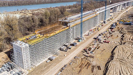


Clear the way for the new Čortanovci Viaduct on the Budapest-Belgrade high-speed line
The Budapest-Belgrade line is part, and the first stage, of the planned international railway connection Budapest-Belgrade-Skopje-Athens and is currently one of the largest investment and infrastructure construction sites in the eastern part of Europe. PERI supported the construction of the Čortanovci Viaduct on the Serbian section between Stara Pazova and Novi Sad - and in addition to intensive on-site support, also provided cleverly combinable system solutions based on the modular principle.
24
Feb
Christian Schwörer takes over as Chairman of the Management Board of PERI GmbH
Christian Schwörer, current Chairman of the Advisory Board of the PERI Group, will be appointed CEO of PERI Group for a transitional period of initially 12-18 months.
12
Jan
Personnel Change in the Group Management of PERI GmbH
Dr. Fabian Kracht, Managing Director Finance & Organisation and Spokesman of the Group Management of PERI GmbH, has decided to leave the company by 30 June 2021 at the latest and start his own business.
08
Jan
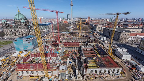


Concrete and baroque: formwork and scaffolding for Berlin's Humboldt Forum
With the Humboldt Forum, a centre of art, culture, science and education opened in the historic centre of Berlin in December 2020. PERI supplied a large quantity of economical formwork and scaffolding solutions from a single source for the reconstruction of the Berlin City Palace. In addition to this well thought-out overall solution, the project support provided by PERI engineers during construction ensured that all requirements were met and the construction schedule was adhered to.
15
Dec
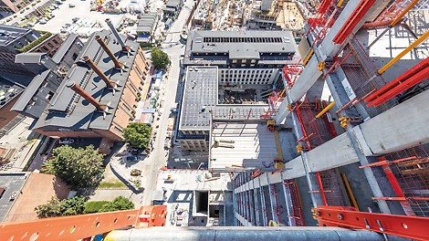


Première of SKYMAX Large Panel Slab Formwork at the construction of Pasteurs Tower in Copenhagen
In Carlsberg City, a district in the heart of Copenhagen, a completely new neighbourhood is being built. Several high-rise buildings are currently under construction there, and Pasteurs Tower will be the highest residential building in Copenhagen upon completion. Flats will be built on 33 of the 37 floors, and commercial enterprises will be located on four floors. PERI supported the project with a variety of formwork solutions. The special highlight: The first use of SKYMAX Large Panel Slab Formwork.
17
Nov
PERI builds the first 3D-printed apartment building in Germany
PERI GmbH has set about printing another residential building using a 3D construction printer, this time in Wallenhausen, Bavaria. At the end of September 2020, the family-owned company announced that work had begun on Germany’s first printed residential house in Beckum, North Rhine-Westphalia. Only two months later, work has begun on the next residential building to make use of 3D construction printing technology. Upon completion, the 5-in-a-block apartment building with around 380 square metres of living space will be the largest printed residential building in Europe. On this project, the printing process is expected to take six weeks.
02
Nov
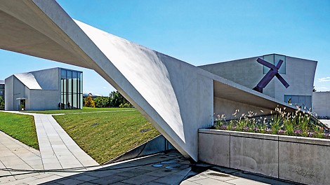


PERI Architectural Concrete Project “The REACH” wins ACI Overall Excellence Award
The building extension at the imposing Kennedy Center for the Performing Arts is commonly known as “The REACH”. It comprises three interconnected pavilions that stand out due to their exceptional architectural design and architectural concrete of the highest quality. The larger-than-life project won the American Concrete Institute’s Overall Excellence Award in October 2020 and is thus recognised as a project that unites particularly creative techniques with innovative technologies. For this special construction project, PERI developed a formwork concept that combined tried-and-tested standard systems with project-specific solutions.
29
Sep
PERI builds the first 3D-printed residential building in Germany
PERI GmbH is building Germany’s first 3D-printed residential building in Beckum, North Rhine-Westphalia. The two-storey detached house with approx. 80 sqm of living space per floor is not being constructed in the conventional manner, it is being printed by a 3D construction printer.
09
Sep
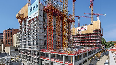


Project-specific solutions using unique combination of formwork and scaffold systems
Thanks to a competent support service and well-thought-out system utilisation, PERI is successfully constructing the complex building geometry of the three TrIIIPle residential towers on the Danube Canal in Vienna, which is subject to stringent requirements. Safe working processes, optimised construction site logistics and cost-effective solutions see demanding building schedule adhered to.
04
Aug
PERI sells first 3D construction printer
Röser GmbH opts for 3D construction printer from PERI Successful conclusion to resolute development work of the past few years Printing technology shows huge potential for a wide range of construction applications
03
Aug
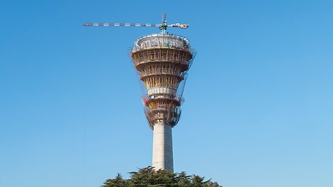


Keeping an eye on everything: a new control tower for Buenos Aires-Ezeiza Airport
With a total surface area of around 7,000 m², a height of 108.40 m and a 360° field of vision over the airport complex, the new air traffic control tower at Buenos Aires-Ezeiza Airport provides the basis for optimised visual monitoring and control of air traffic. PERI assisted with the complex construction work by providing tailor-made special-purpose formwork, closely coordinated formwork and scaffolding solutions, and much more.
01
Jul
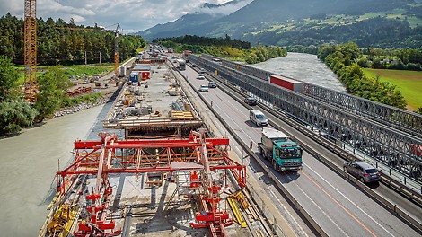


Reconstruction of the “Terfener Innbrücke” bridge on the A12 motorway in Austria’s Inntal valley
The Terfener Innbrücke reconstruction project on the A12 motorway in the Inntal valley is one of largest bridge construction projects currently being carried out in the west of Austria. With PERI by their side, the client has been successful in implementing the project according to the demanding construction schedule since construction began in 2018. In addition to providing comprehensive planning services and on-site support during the project, PERI has also made use of the VBC Balanced Cantilever Carriage for the first time in Central Europe.
04
May
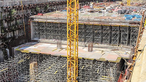


Bandra Kurla Complex (BKC): PERI assists with the construction of Asia’s largest underground station
The Bandra Kurla Complex (BKC) is an underground station on the Mumbai Metro, a rapid transit system that is currently under construction. The rapid transit system in the Indian metropolis will serve the city of Mumbai itself as well as its entire metropolitan area in the federal state of Maharashtra. By supplying comprehensive formwork and scaffolding solutions, PERI has been providing assistance since construction began on the major project in April 2019 so that the BKC can be completed within the demanding construction time-scale of only 14 months.
01
Apr
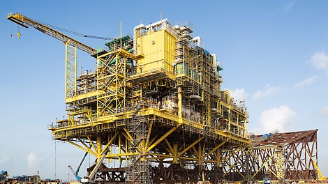


New platform for the Mexican oil and gas field Ku-Maloob-Zaap
The oil and gas field Ku-Maloob-Zaap (KMZ), which covers a total area of around 121 km², is situated in the bay of Campeche, 105 km north-east of the city of Ciudad del Carmen. In 2019, a new gas compressor platform named CA-KU-A1 was added to the oil and gas production complex that is located there. To carry out the time-critical construction project, PERI provided flexible scaffolding solutions and comprehensive on-site support.
02
Mar
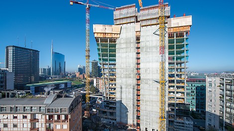


Innovative and sustainable: PERI assists with the construction of the office complex GIOIA 22, Milan
GIOIA 22 is setting new benchmarks in terms of sustainability: the 120 m tall tower at the heart of the Porta Nuova district will cover 65 percent of its annual energy requirements using renewable energy sources. The 30 storey tall building will provide enough space for approximately 2,700 people, 350 parking spaces and 13 lifts. PERI provided support during the construction process of this inventive project using a combination of tailor-made formwork and climbing solutions.
03
Feb
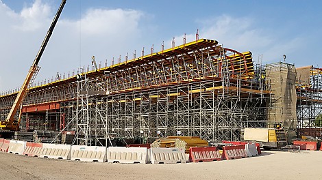


Demanding infrastructure project underway in Doha
Adherence to deadlines, efficiency and completion without interrupting the flow of traffic are the requirements that are of paramount importance during the Sabah Al Ahmad Corridor infrastructure project. For the construction phase on Al Bustan Street South, PERI made use of the PD 8 shoring system and a combination of systems from the PERI UP Flex portfolio in addition to a tailor-made VARIOKIT solution with VST heavy-duty shoring towers. The customer has therefore taken full advantage of the opportunity to procure time-saving formwork and scaffolding systems from a single source.
03
Feb
PERI canteen awarded third best canteen in Germany!
The canteen at the PERI headquarter in Weissenhorn has achieved 3rd place in the Germany-wide canteen test carried out by the magazine FOCUS and Food & Health e.V.
23
Jan
PERI wins Office Excellence Award 2019
PERI GmbH has received the Office Excellence Award 2019. With this award, companies are honoured for extraordinary success in the implementation of measures to increase efficiency in the office area. In recent years, Volkswagen, Daimler, Viessmann and Schmitz Cargobull were among the winning companies.
10
Dec
PERI opens new vocational training centre at its Weissenhorn headquarters
PERI today opened the company's new vocational training centre at its headquarters in Weißenhorn. In total, the family-owned company is investing a single-digit million Euro amount in the new training facility.
06
Dec
Awards for the prize winners of the 12th PERI Construction Exercise
PERI offers all educational institutions involved in the field of construction the opportunity to participate in its well-known Construction Exercise, which not only provides valuable experience with specific practical application but also the chance to win attractive cash prizes.
02
Dec
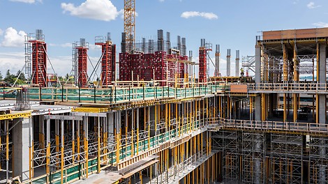


Wide range of PERI system solutions used during construction of the Calgary Cancer Centre
The building of the Calgary Cancer Centre, a state-of-the-art cancer treatment and research centre, is not only the largest construction project currently being carried out in the province of Alberta in Canada, it is also the largest construction project PERI has ever taken on with regard to the volume of material on site. The use of 14 different perfectly coordinated PERI system solutions has made it possible to realise the complex design of the centre in an efficient manner.
02
Sep
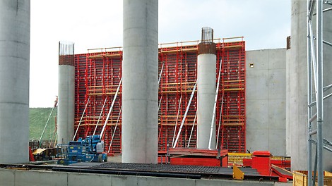


PERI systems in use for construction of a new airport in Istanbul
Istanbul Airport can accommodate around 90 million passengers per year but can easily be expanded in order to handle up to 200 million passengers annually. Two gigantic terminal buildings have been planned to deal with this enormous increase in passenger volume - the first terminal alone provides 1.44 million m² of effective area. Various PERI systems were used in the construction of the terminal building as well as for realising other structures.
01
Aug
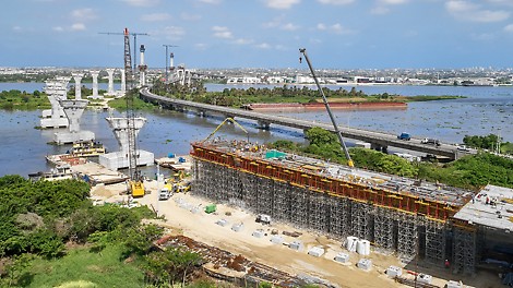


Record-breaking bridge successfully completed with PERI systems
The new cable-stayed bridge over the Rio Magdalena is 2.3 km long. PERI engineers supported the challenging construction project by providing a customised formwork and scaffolding solution that has been designed for realising the simultaneous construction of the pylons, bridge piers along with the superstructure. The versatility of the formwork and scaffolding systems as well as the combination possibility with the VARIOKIT Engineering Construction Kit facilitated shortened assembly times also when dealing with complex geometries.
10
Jul
Innovation Award for PERI
The association "Die Familienunternehmer" has awarded the Bavarian Family Entrepreneur Prize for the eighth time. With this award, the association honors the commitment of family businesses to their respective regions. In 2019, PERI received the award as Bavarian family enterprise of the year in the category innovation.
01
Jul
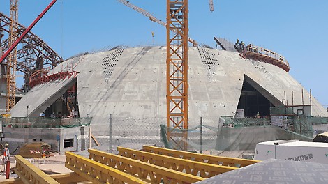


Extraordinary architectural project combines tradition and modernity
As part of the Kuwait University's Student Activities and Athletic Facilities Project (SAAF) in Al-Shadadiya, an indoor tennis centre is currently being realised. The training centre will provide athletes and students with an area of 7,100 square metres in order to carry out their daily training activities. In addition, the building also has three floors and space for around 2,000 spectators. Externally, the sports venue impresses with its dome-shaped roof in the style of traditional Islamic architecture. PERI planned and delivered a project-specific solution for facilitating the efficient execution of the architecturally sophisticated dome-shaped building.
03
Jun
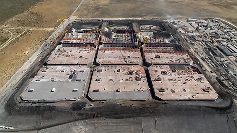


Unconventional VARIOKIT solution for underground tanks
Covering the size of 24 football pitches, 17 m high and having sufficient capacity to store a total of 13.2 million barrels of oil: in Saldanha Bay, South Africa, a huge crude oil tank farm featuring twelve 110 m x 110 m tanks has been realised. The clients of WBHO Construction Ltd. integrated the team of PERI engineers into the project at a very early stage so that they could work together to develop the most appropriate solution for the gigantic task ahead already during the planning phase. The most cost-effective method for constructing the underground tanks proved to be a project-specific solution using the VARIOKIT steel composite carriage with additional specially designed structural steel members.
02
May
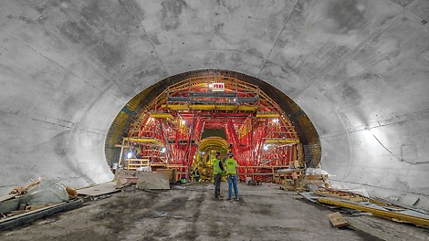


VARIOKIT tunnel formwork solution deep in the heart of the Golden City
With construction work being carried out in depths up to 30 metres in the centre of the city famous for the Golden Gate Bridge, an enormous building structure is being realised. When completed, the Chinatown Subway Station will form the northern end of San Francisco's Central Subway System. The new station will significantly improve access to public transport in some of the city's most densely populated areas. The architectural requirements presented the contractor with enormous challenges. PERI developed a project-specific solution based on the VARIOKIT Engineering Construction Kit in order to economically construct the inner lining.
12
Apr
New products at the leading global trade fair bauma
Weissenhorn / Munich. Under the motto "Hand-in-Hand for Your Success", PERI presented a range of innovative new products for formwork and scaffolding technology at the bauma which took place from 8th - 14th April. Individual customer requirements of various target groups were the main focus of the respective product development. In keeping with its motto, PERI also presented its extensive range of services and software some of which could be tested directly on the stand.
20
Mar
PERI relies on CADENAS for BIM CAD scaffolding component library
Architects, planners, work planners and civil engineers can now download more than 200 scaffolding components in over 150 CAD formats at no cost.
11
Feb
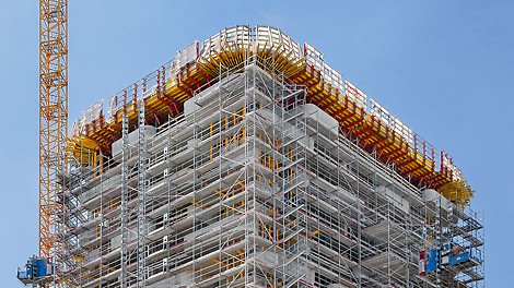


Green residential tower grows with VARIOKIT
The Aglaya high-rise building is situated in the so-called Suurstoffi area in Risch Rotkreuz next to Lake Zug. In a unique way, it combines the increasing desire of living in a green environment with careful management of building land resources. PERI planned and delivered a scaffolding and formwork solution to meet the difficult formwork challenges of this flagship project for realising a future-oriented living environment.
01
Feb
PERI at bauma 2019
Weissenhorn / Munich. At the industry´s leading international trade show from 8th to 14th April 2019 in Munich, PERI will be showcasing numerous new developments for formwork and scaffolding technology to customers and visitors alike. The focus is on innovations, practice-oriented system supplements as well as further developments which cover a wide range of applications and target groups. An important feature of the company´s trade fair appearance is that of digital solutions along with the comprehensive range of services that PERI uses to make project realisation regarding all aspects of formwork and scaffolding more economical and safer for all users.
16
Jan
PERI DUO wins BAKA Prize for Product Innovation 2019
Weissenhorn-based formwork and scaffolding manufacturer, PERI, has won the BAKA Product Innovation Award 2019. Gunther Adler, State Secretary at the Federal Ministry of the Interior responsible for construction and homeland affairs – together with Dr. Ing. Reinhard Pfeiffer from Messe München and BAKA Chairman Ulrich Zink – presented the award in front of around 800 invited guests at the BAU 2019 in Munich on 14th January. The special award was accepted on behalf of the company by Bernhard Überle, PERI Sales Director Germany, and PERI Sales Manager, Helmut Sterflinger.
12
Dec
Construction Symposium: PERI brings universities up-to-date on latest developments
On 27th and 28th November 2018, formwork and scaffolding manufacturer PERI held its traditional symposium for professors – this was the ninth time the event had been organised. More than 30 lecturers from construction faculties of German and Austrian universities took advantage of the opportunity to obtain detailed and practical information about the current state of formwork and scaffolding technology at the advanced training centre in Weissenhorn. The main focus was on process optimisation on construction sites as well as BIM and open innovation.
10
Dec
Best digital service for customers
The digital world of today means changes on a daily basis. Under the motto “The best possible solution for our customers”, the Weissenhorn-based company has now made the most important PERI wall, slab and column shuttering systems available in the Tekla Warehouse. As a result, this has significantly expanded the cooperation that has existed since 2016 and will allow planners in particular to benefit in future from the advantages of Building Information Modelling without sacrificing the convenience of their familiar software environment.
07
Dec
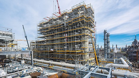


Innovative BIM scaffolding concept in industrial construction
At BASF SE in Ludwigshafen, a new state‑of‑the-art acetylene plant is currently being built. The basis for the construction of the facility is an innovative, BIM‑based scaffolding concept as well as the PERI UP scaffold system with its high level of flexibility for ensuring consistently safe work operations.
04
Dec
Excellent: PERI one of the best “Vocational Trainers in Germany"
The family business PERI is among the best vocational training companies in Germany. In a Germany-wide study by the business magazine "Capital", both the vocational training as well as the dual studies at PERI received the highest possible marks.
09
Nov
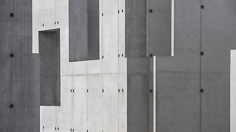


A bold concrete structure built entirely with DUO formwork
Over the past year, a concrete structure has slowly emerged amongst a more conventional residential setting in East Sussex. The single-storey structure is the first self-build project the owner, Adrian Corrigall, has ever built. At the same time, it’s also PERI’s first housing project with DUO in the United Kingdom.
06
Nov
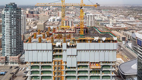


PERI‘s ACS Core 400 and RCS climbing systems push forward with redevelopment of city landscape
Downtown Edmonton is seeing a significant transformation with the development of the ICE District. The complete redevelopment includes premium residential, retail, public and office spaces in one location. The skyline is dramatically changing as large scale projects continue to rise, including the 66-storey Stantec Tower. PERI has been involved with the project from the beginning, working together with PCL and Newway to provide professional engineering solutions and logistical support.
30
Oct
PERI Group acquires stake in COBOD International A/S
The PERI Group, one of the world's leading companies in the field of formwork and scaffolding for the construction industry, acquires a stake in the Danish 3D concrete printing specialist COBOD International A/S based in Copenhagen.
02
Oct
Changes in the Management of the PERI Group
Due to differing views on the concept of leadership and management, Dr. Rudolf Huber, Chief Executive Officer (CEO) of the PERI Group, is stepping down from office by mutual agreement as of September 30, 2018.
04
Sep
Extraordinary formwork for an extraordinary building
Inspired by cliffs of sedimentary rock standing proud against the sea, at the centre of Dundee’s £1 billion waterfront regeneration, lies the V&A Museum of Design. This £80.11 million masterpiece, the first UK work penned by renowned Japanese architect Kengo Kuma, is a bold creation combining complex concrete architecture with glass facades and linear concrete cladding. PERI has provided professional engineering services and bespoke formwork solutions in order to achieve the best possible architectural concrete result.
01
Aug
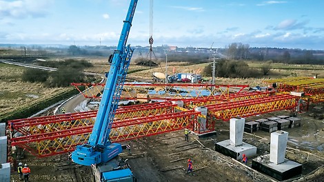


Premiere for the VARIOKIT Heavy-Duty Truss Girder in Poland
For realising a demanding bridge construction in the wetland area near Szczecinek, PERI engineers planned a project-specific shoring and formwork solution. Heavy-Duty Truss Girders and Heavy-Duty Truss Towers based on the VARIOKIT Engineering Construction Kit safely transferred the high loads via large spans and into the ground; VARIOKIT formwork units along with the customised formwork solution were supported on this. The first use of the truss girders convinced the construction team due to the low weight and fast assembly. Factors that facilitated both time and cost savings during the execution.
02
Jul
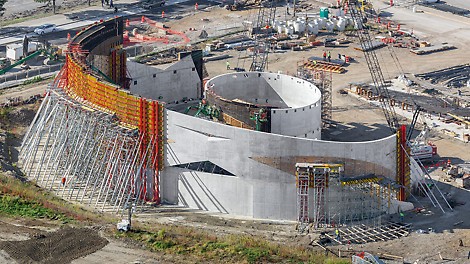


Custom formwork and box-outs precisely form sweeping curves of unique concrete structure
The National Veterans Memorial in Columbus, Ohio will open in the fall of 2018. The elegant, sweeping curves of the three interlaced cast-in-place reinforced concrete rings that define the structure belie the complexity of the project’s design and construction.
24
May
In focus: PERI bundles BIM activities
Weißenhorn. PERI, one of the world's largest manufacturers and suppliers of formwork and scaffolding systems, has been a pacesetter on the road to the future of digital construction for many years now. In 2017, the family‑owned company founded a Digital Transformation Office whereby all of PERI's digitalization‑related strategic activities and initiatives would be grouped together and coordinated. Furthermore, the PERI BIM Competence Center, which has existed since 2015, has also been integrated into the Digital Transformation Office.
02
May
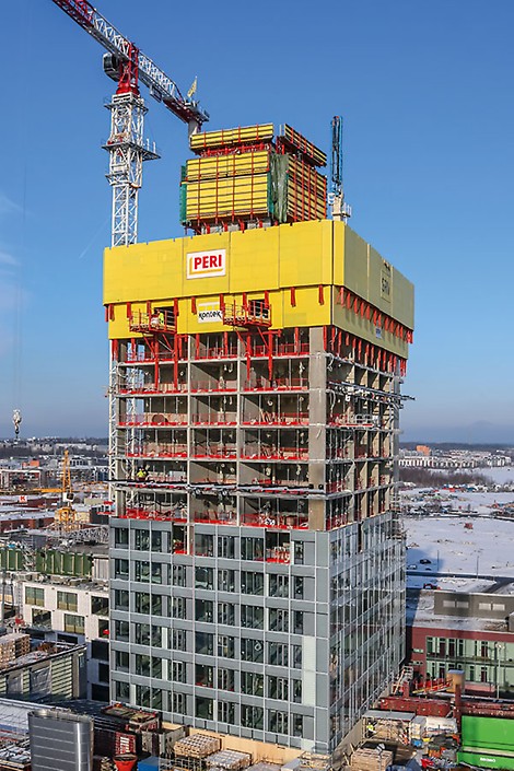


Majakka reaches for the clouds – first residential tower in Finland
The tallest residential building in Finland – the 134 m high REDI Majakka Tower – is currently under construction in the old harbour district in the eastern part of Helsinki´s city centre, in the heart of Kalasatama. With the experience and competence resulting from countless projects worldwide in the area of climbing technology, PERI engineers have been supporting the construction team in the planning and efficient implementation of Finland's largest inner-city construction site.
10
Apr
Fast construction progress thanks to a safe and coordinated scaffolding and formwork solution
For the construction of the new terminal building in the port of Gazenica, PERI Croatia planned and supplied a comprehensive formwork and scaffolding solution from a single source. The systems used were perfectly matched to one other and greatly contributed to ensuring safe and time-saving execution through efficient work procedures. The stringent demands in terms of occupational safety and surface quality could be met in spite of the complex building geometry and the need for large supporting heights.
01
Mar
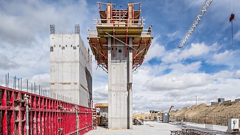


Fast striking and easy climbing with the MAXIMO Shaft Corner
For realization of the Hexagon Headquarters in Calgary, reducing labour costs and execution times as well as minimizing the usage of the cranes for faster forming operations, was the main focus of attention for the construction company. By combining MAXIMO Panel Formwork with CB Climbing Units, not only could the required, high-quality concrete surfaces be achieved along with maintaining the tight schedule, but also ensured high safety and productivity levels of site personnel.
01
Feb
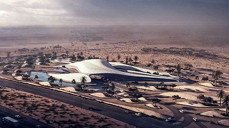


Zaha Hadid's dunes for the desert in UAE’s eastern district
In the middle of the Sharjah Desert in the United Arab Emirates, a futuristic building is currently being constructed according to the plans of Zaha Hadid. As inspiration, the famous architect used nothing more than sand dunes. PERI is supporting this ambitious project with an individually-designed planning solution, project-specific formwork elements as well as by providing comprehensive support through its local team of experts.
19
Jan
Groundbreaking ceremony for the next expansion phase of the PERI plant in Guenzburg
PERI GmbH sets course for further growth. The family-owned company, one of the world's largest manufacturers and suppliers of formwork and scaffolding systems, is massively increasing its production capacities. Today, the official groundbreaking ceremony for the next expansion phase of the scaffolding plant in Guenzburg, Bavaria, took place.
08
Jan
Project-specific formwork solution with high level of prefabrication
The realization of the new, second Moselle lock presented a challenging construction project for all those involved in the undertaking whereby numerous mounting components and strict tolerance specifications had to be taken into consideration. Working in close cooperation, PERI supported the construction site managers from Hochtief Infrastructure GmbH with a project-specific formwork and scaffolding concept, just-in-time deliveries of accurately pre-fabricated formwork elements as well as continuous on-site support.
12
Dec
Expert jury determines the winners of the 11th PERI student competition
PERI offers all educational and training institutions involved in the field of construction the opportunity to participate in its well-known Construction Exercise, which not only provides valuable experience with specific practical application but also the chance to win attractive cash prizes.
04
Dec
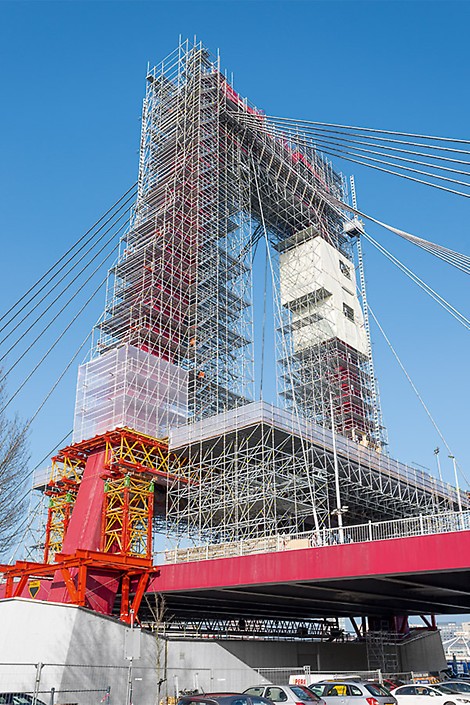


PERI system combination for challenging pylon scaffolding
The refurbishment of the pylons on Rotterdam's Williams Bridge proved to be a tremendous challenge for installing the scaffolding. The project-specifically designed PERI scaffold solution was based on two systems that could be combined with each other almost seamlessly: PERI UP and VARIOKIT.
01
Dec
Changes in the Advisory Board and in the Group Management of the PERI Group
The shareholders and the Advisory Board of the PERI Group have decided to change the management organization of the family-owned company: As of January 1, 2018, the Group Management of three managing directors, will be extended by a Chief Executive Officer (CEO) and thus, from this date on, will consist of four persons.
23
Nov
The PERI UP Modular Scaffolding Kit – more system in scaffolding operations
Safety requirements on construction sites are steadily increasing, scaffolding projects are becoming more and more complex and the cost pressures companies are facing is high. As a result, this not only changes the day-to-day challenges for the contractors but also the demands placed on the scaffold systems themselves. The question therefore arises whether a rigid differentiation of frame and modular scaffolding is still relevant today. After all, the market demands a product that contains both frame and modular scaffolding features as well as having the right solution in the system ready for every task. The PERI UP Modular Scaffolding Kit fulfills this requirement in every respect.
02
Nov
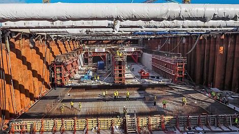


Underwater tunnel connects the banks of the Göta älv river
One of the most interesting tunnels in Scandinavia, the Marieholm Tunnel, is currently being realized in the city of Gothenburg. In future, the 306 m long underground connection will ensure that the river Göta älv can be quickly crossed using the available six vehicle lanes. The structure is being constructed in the form of an immersed tunnel: three tunnel sections, each measuring more than 100 m long, are being produced in a dry dock with the help of a PERI VARIOKIT Tunnel Formwork Carriage and will subsequently be submerged in a trench excavated on the riverbed.
05
Oct
Planning PERI formwork systems in Autodesk® Revit®
Autodesk® Revit® software for Building Information Modelling (BIM) includes functions for architectural planning and design, building technology, structural engineering and construction. Interested users can now integrate the PERI product catalogues for formwork systems MAXIMO and SKYDECK in Revit® and plan in the software using PERI system components.
28
Sep
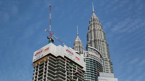


Luxury hotel construction ahead of schedule thanks to comprehensive PERI support
Situated in the shadow of the famous Petronas Towers, one of the most luxurious hotels in the world is currently being realized. For the building complex – the so-called Four Seasons Place – the PERI engineers developed an efficient scaffolding and climbing formwork solution. The most important goal was to facilitate efficient work operations and, at the same time, provide a high degree of safety for the personnel on site. Result: construction process is far ahead of the original planned schedule.
27
Sep
Official opening of scaffold production in Günzburg / Bavaria
Weissenhorn‑based PERI GmbH has planned further growth in its scaffolding division and to this end has created the required production capacities. As any expansion possibilities at the main plant in Weissenhorn are limited, a new manufacturing facility in the neighbouring town of Günzburg is beeing build since January 2016. The primary plant for the PERI UP scaffolding technology was officially opened on 22 September 2017.
04
Sep
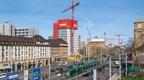


Virtually unnoticed: Demolition work on high-rise building within RCS enclosure
The Swiss agricultural company, Syngenta, is completely transforming its headquarters in the centre of Basel. For this, a 54 m high tower block had to be removed. Due to the position of the building which is directly adjacent to the corporate campus as well as in close proximity to the highly frequented Schwarzwaldallee and the Badischer Bahnhof, demolition using large demolition excavators was out of the question. PERI engineers in collaboration with contractor ERNE AG developed a concept on the basis of the RCS Rail Climbing System which allowed a safe and efficient dismantling of the structure within an all-round enclosure.
01
Sep
A decade of maximum efficiency for forming walls
Presented for the first time at the bauma 2007, the MAXIMO panel formwork continues to make a convincing case even a decade later through its enormous economic efficiency. In particular, the tie technology that was developed ten years ago by PERI leads to significantly smaller numbers of jobsite personnel thus resulting in considerable time and cost savings. Over the years, PERI engineers have continually expanded the application areas of this innovation. This is why the PERI MAXIMO can be found on countless construction sites in Germany and around the world.
03
Aug
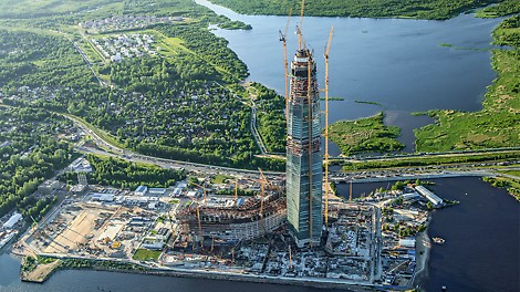


Formwork and scaffolding from one source for the highest skyscraper in Europe
With its very impressive architecture, the Lakhta Center, a futuristic building complex designed by Tony Kettle, is the new highlight of Saint Petersburg. Eventually rising to a height of 462 m, the multi-storey building in the centre of the complex will not just surpass all other structures in Russia when it is completed. Rather, the high-rise building on the Finnish Jade Bight will be the tallest building in Europe. Faced with numerous formwork and scaffolding challenges, PERI has been providing the contractor with expert support throughout the project – from formwork solutions for the record-breaking foundations through to complex shoring arrangements.
01
Jul
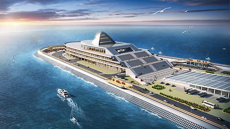
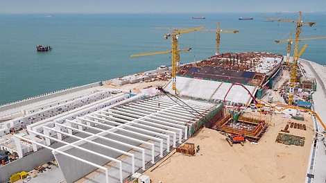
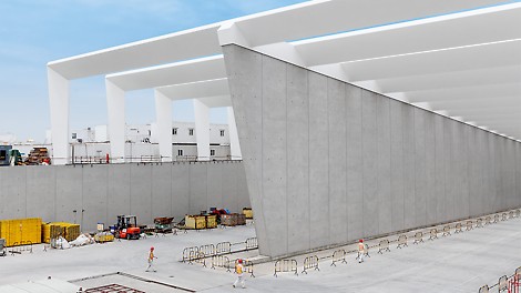
With PERI know-how and support for the best architectural concrete quality
Since 2010, PERI has been supporting the construction of the 6 km long underwater tunnel section of the fixed link between Hong Kong and Macao / Zhuhai with the provision of two forming machines. The excellent cooperation has led to additional orders: PERI has provided professional engineering services and project‑specific formwork solutions for achieving the best possible architectural concrete results as well as large time‑savings during construction work for the tunnel portals and two operation buildings.
01
Jun
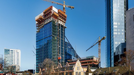
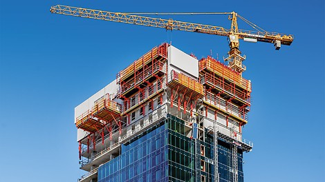
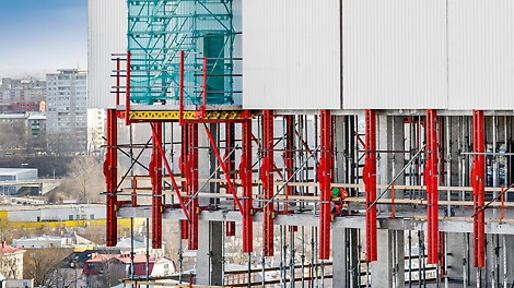
Fast high-rise construction progress with a well thought-out formwork concept
A total of seven buildings characterize the Maakri-Kvartal complex which is currently being built in the Estonian capital. The project comprises new high-rise buildings as well as restored architectural monuments and connects the historical heart with the newer district of Tallinn. PERI developed and delivered corresponding formwork solutions for the new structures as well as the renovation work. The PERI team has supported the rapid construction progress in particular with climbing technology for the city´s new landmark – a high-rise building with a height of more than 100 m.
02
May
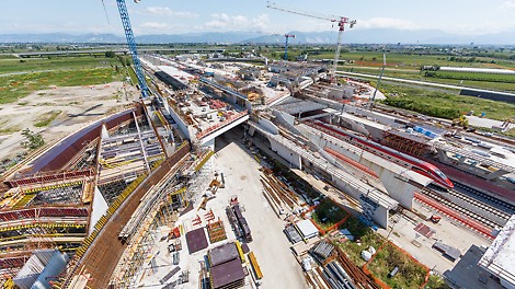
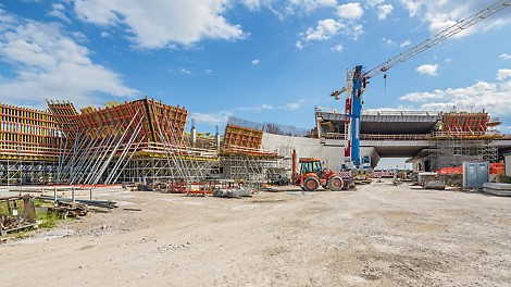
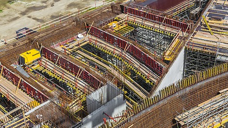
Comprehensive PERI solution for the very impressive "Doorway to the South"
At the beginning of June 2017 the “Porta del Sud” near Naples is scheduled to be opened. Christened with this name, the ultra-modern railway station for high-speed trains in Naples Afragola forms the major intersection on the Rome-Neapel-Salerno line. The bold architectural design of the station bears all the hallmarks of Zaha Hadid. PERI developed a comprehensive formwork and scaffolding solution for the realization of the curved architectural language of the famous architect.
03
Apr
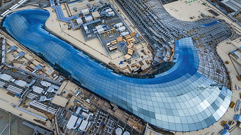

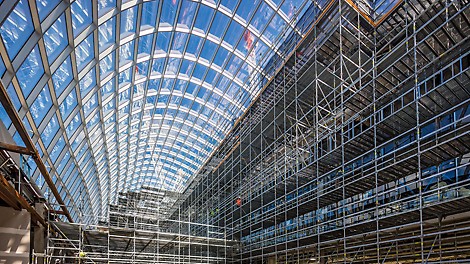
PERI UP for an architectural highlight ”Down Under“
In Melbourne, the continent´s largest shopping centre has been renovated and expanded. Now an architecturally demanding, curved glass construction covers the Chadstone Shopping Centre which was opened in 1960. For the scaffolding contractor, the biggest challenge was to meet the extremely tight timetable in spite of only minimum crane availability. The project-specific planning service provided by PERI Australia´s engineers, together with the system advantages of the flexible PERI UP Flex Modular Scaffolding, helped the construction team to complete the work within the very tight time schedule.
03
Mar
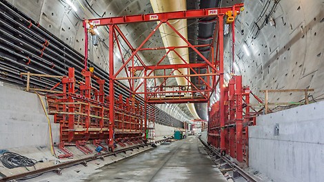
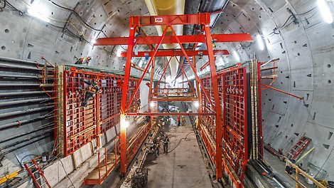
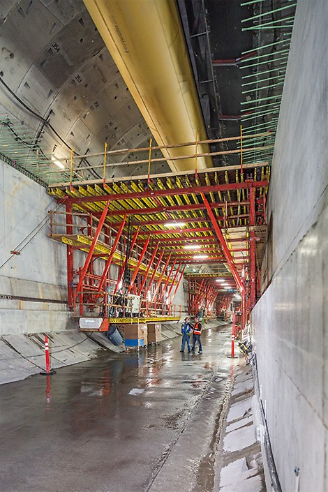
PERI Formwork Carriage follows one of the world´s largest tunnel boring machines
As a replacement for the elevated viaduct that is used daily by 110,000 vehicles, a 3.2 km long tunnel is currently being constructed. PERI planned and delivered a project-specific formwork solution for the realization of the double-storey carriageway whereby the previously drilled tunnel tube length is being concreted in three sections each time.
09
Feb
DUO Market Launch in the US
PERI USA launches a new lightweight formwork system made from fiber reinforced polymer. The versatile panels feature 3 in 1 functionality and can be used to form walls, slabs and columns.
01
Feb
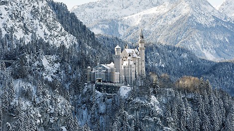
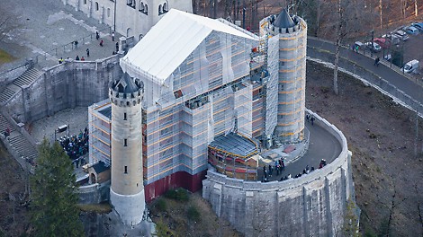
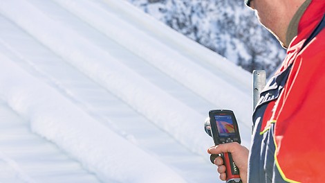
Well equipped and heated through the winter
For scaffolding and enclosure of the gateway building, the PERI UP Flex scaffold solution has been optimally adapted to suit the local site conditions and static requirements. The exclusive use of system scaffolding components thereby accelerated the assembly work and, at the same time, increased safety levels during the use of the scaffold. For the first time in scaffolding, heatable roof tarpaulins ensure that the formation of unwanted snow loads are prevented during the winter months.
30
Jan
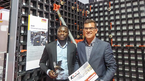
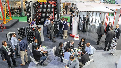
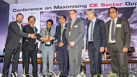
PERI DUO continues to garner additional awards
The PERI DUO universal formwork system continues to attract a very positive response: two more bodies - one in Angola, another in India – have awarded the new technopolymer-based formwork with corresponding innovation prizes.
23
Jan
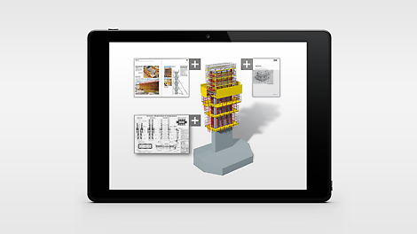
Practical applications for BIM
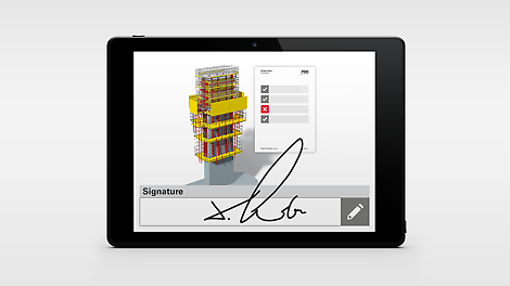
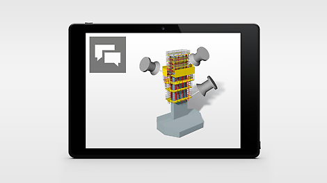
PERI is currently planning the formwork and scaffolding solution for the construction of the Filstal Bridge on the Wendlingen-Ulm rail connection. This bridge was defined by the Federal Ministry of Transport and Digital Infrastructure (BMVI) as one of four pilot projects whereby the application of Building Information Modeling (BIM) is being tested and scientifically evaluated. This article describes some specific BIM practical applications which PERI has defined and implemented on this bridge in close collaboration with the contracting JV, Max Bögl / Porr.
19
Jan
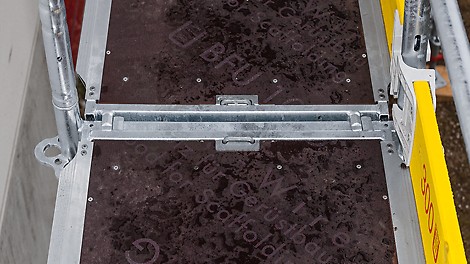
From planning to implementation
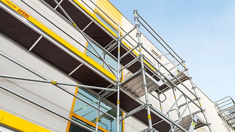
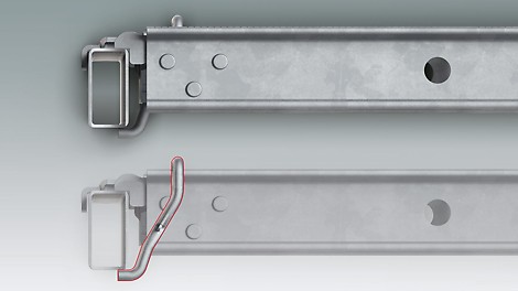
Enhanced safety along with maximum flexibility: the new PERI UP Easy* facade scaffold system solves two of the most important challenges faced in day-to-day construction site operations as the new frame scaffold supports safe and fast assembly. In addition, the integrated scaffolding nodes allows PERI UP Easy to be combined with the PERI UP Flex modular scaffolding thus ensuring maximum flexibility even when dealing with complex building geometries. Furthermore, PERI offers its customers a wide range of services relating to planning, tendering and project execution through to the entire planning and construction process.
19
Jan
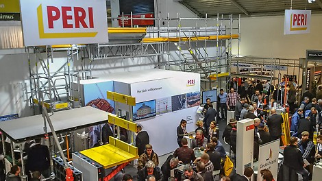
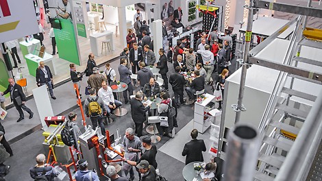
Innovative Systems for craft producers – Competence in project solutions for planners
What can one of the largest internationally operating suppliers of scaffolding and formwork systems possibly offer smaller construction companies, tradesman or municipal building enterprises? And with what services does the manufacturer also support the planning phase for construction projects? PERI answered these questions and much more to visitors at the BAU 2017. At the beginning of the year, PERI presented in Munich great solutions to trade fair visitors – and gained particularly positive acclaim.
09
Jan
09
Jan
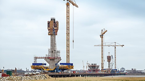
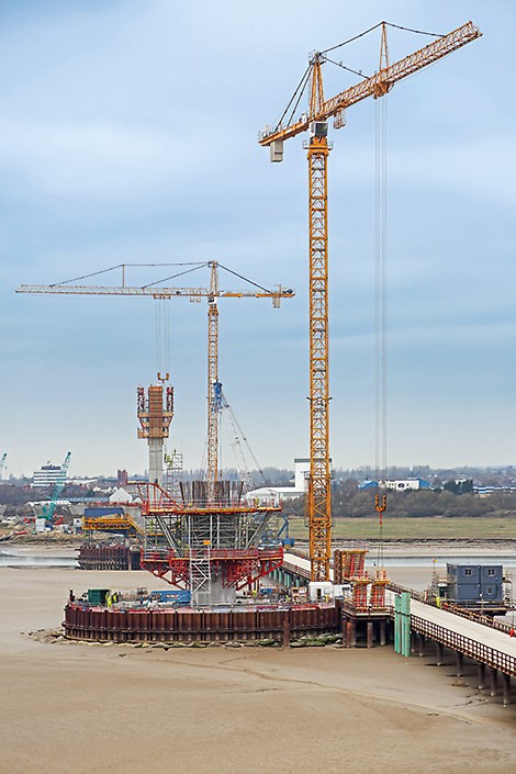
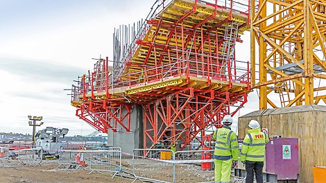
Landmark Mersey Gateway on form with help from PERI
Merseyside in North-West England is embracing significant improvements to its transport systems thanks to the landmark construction of the Mersey Gateway. The road bridge over the River Mersey is an integral component of the new A533 Central Expressway. Located 20 km east of Liverpool, it will provide an important transport connection between the towns of Runcorn in the south and Widnes in the north.
23
Dec
Targeting worldwide growth
PERI can look back with great satisfaction at events in 2016 and retains a positive outlook regarding future business development. Special highlights of the year included participation at the world´s leading trade fair, bauma, where the latest innovations from Weissenhorn were showcased as well as the purchase of a site in Günzburg (about 20 km from headquarters in Weißenhorn) on which the master production plant for PERI UP scaffolding technology is currently being realized. As a result, PERI has provided the right impulse and set the course for the future.
16
Nov
Specialist symposium on construction operations: PERI demonstrates latest know-how to the universities
On 8/9th November 2016, formwork and scaffolding manufacturer, PERI, invited university professors for the eighth time to the company´s headquarters. At the training centre in Weissenhorn, more than 40 lecturers from civil engineering faculties in Germany and Austria took the opportunity to get in-depth and practical insights into state-of-the-art construction methods in the area of formwork and scaffolding technology. The main focus was on new and further developed systems, online services and various aspects in research and development.
11
Nov
Efficient planning ensures optimal material availability worldwide
At the beginning of October 2016, PERI once again proved that the company continues to operate at an international level in terms of innovation: at a logistics conference, the Supply Chain Management department was awarded the "Supply Chain Management Award 2016" for its innovative logistics concept. Excellent planning is not just a requirement of the company but is in fact indispensable in order to provide customers with the appropriate formwork and scaffolding systems at all times. The innovation prize confirms that the solution developed in the company is indeed first class.
03
Nov
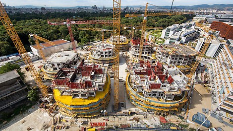
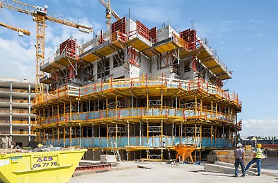
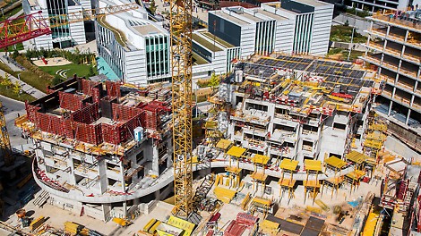
Vienna housing construction project in two-quarter time
With a similar amount of zest and energy as the Viennese Waltz in three-quarter time, seven extravagantly shaped residential towers are currently being constructed adjacent to the famous Prater amusement park in Vienna. Perfectly matched PERI formwork, scaffolding and safety solutions ensure a high concreting cycle frequency in order to meet the extremely tight construction schedule.
05
Oct
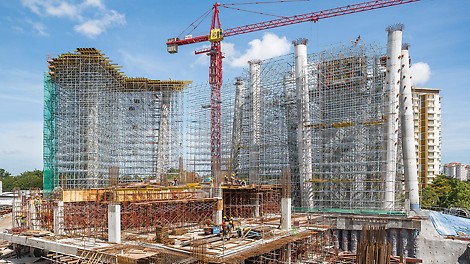
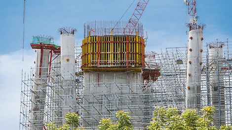
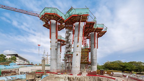
Know-how from a single source for all construction tasks
In the government district of Putrajaya, a new administration building of the Malaysian Anti-Corruption Commission (Suruhanjaya Pencegahan Rasuah Malaysia: in short, SPRM) is being realized. For constructing the elevated high-rise complex, PERI planned and delivered the formwork and scaffolding solution from a single source. The systems used were perfectly matched to one another resulting in a safe and time-saving execution.
05
Sep
Project support at the very highest level
The Henninger Turm, with its very distinctive barrel-shaped top section, was and is once again one of the landmarks of Frankfurt. With formwork, scaffolding and a comprehensive range of services, PERI provided project-specific execution solutions for every stage of the construction from a single source.
03
Aug
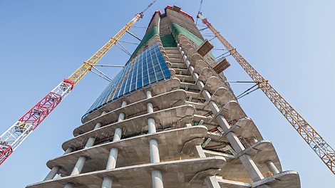
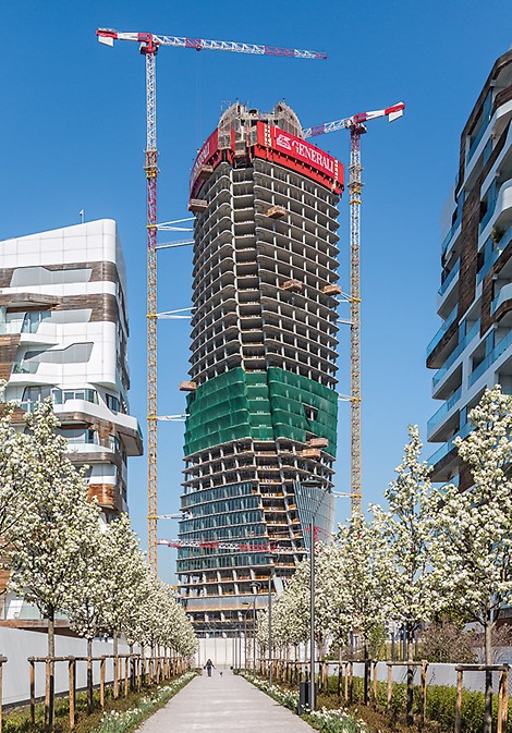
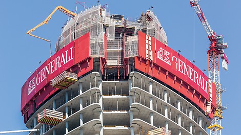
Twisted highrise architecture from Zaha Hadid
The 170 m high office tower in Milan elegantly winds its way upwards and bears the signature of Zaha Hadid. Through the interplay of perfectly coordinated formwork and scaffolding solutions on the basis of a well thought-out safety concept, the shell construction could be completed within just 17 months.
26
Jul
PERI convinces through innovative climbing technology and a very impressive performance
The expansion of the second most important waterway in the world is finished. Since the end of June 2016, large container ships can now also pass through the around 80 km long Panama Canal which connects the Pacific with the Atlantic. For PERI, it meant that the largest individual order in the 47-year history of the company had finally been completed.
03
Jun
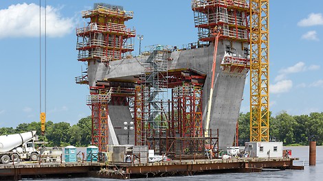
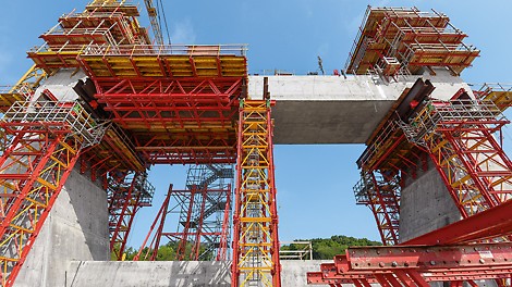
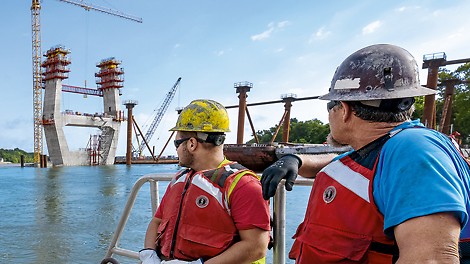
Climbing formwork and shoring solution for complex bridge pylons
The almost 90 m high pylons for a new cable‑stayed bridge across the Ohio River are characterized by their complex shapes and massive legs and cross beams. PERI provided a comprehensive overall concept for its construction – consisting of a planning solution with perfectly matched formwork, climbing, shoring and scaffolding systems along with extensive on‑site support. With this PERI solution, the construction crew were able to realize the two bridge pylons in Louisville within the specified construction period and with low dimension tolerances.
02
May
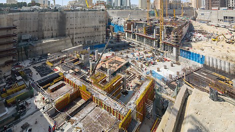
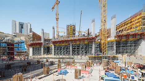
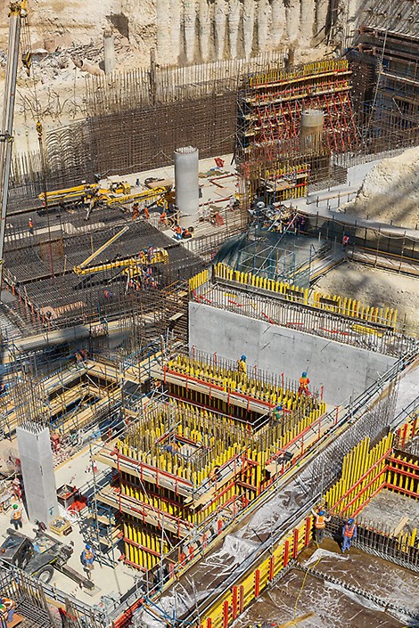
Inner-city major construction site at a depth of 40 m
PERI engineers supported the fast construction progress of the Msheireb Station, the key element of Doha's new metro system, with an individually tailored system concept and continuous on-site support.
19
Apr
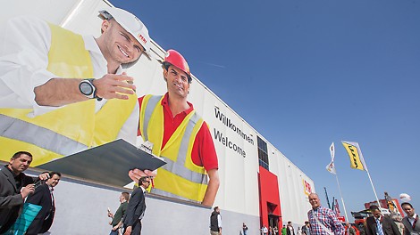
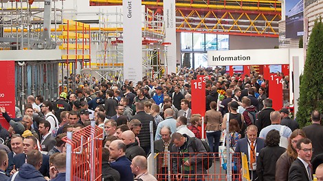
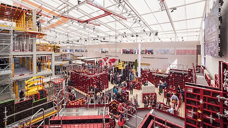
bauma 2016: An outstanding success for PERI
At the 32nd Edition of the World´s Leading Trade Fair for Construction Machinery, Building Material Machines, Mining Machines, Construction Vehicles and Construction Equipment, around 175,000 visitors were recorded at PERI´s specially erected exhibition hall. The biggest attractions featured a number of interesting innovations: DUO Universal Formwork, SKYMAX Slab Formwork and the ACS Core 400 Core Climbing Formwork. PERI Managing Director, Alexander Schwörer, confirmed: "For us, bauma 2016 was a great success, and we are very satisfied with the positive feedback as well as the high quality of the fair visitors."
12
Apr
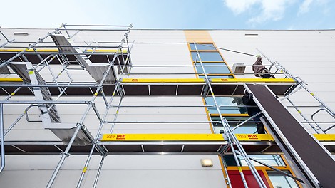
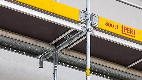

PERI Scaffolding Technology at bauma 2016
Reports about new products for the target group of scaffolding contractors and industrial companies
12
Apr
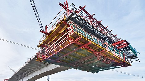
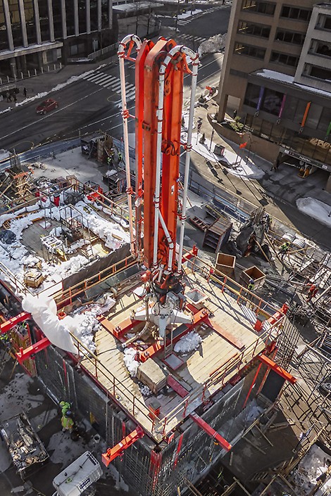
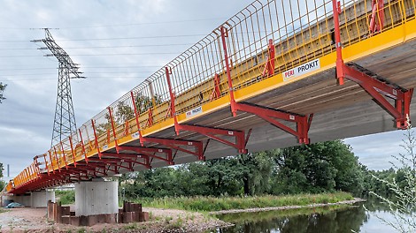
PERI Engineering Construction at bauma 2016
Information about new products for the target group of engineering companies (bridge and tunnel construction; climbing technology)
12
Apr
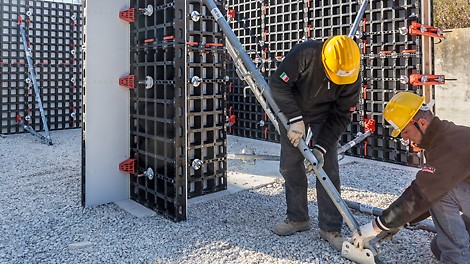


PERI Formwork and Scaffolding Technology at bauma
Information on new products for the target group of contractors in building construction; reports about new formwork systems as well as shoring solutions and the weather protection roof
12
Apr

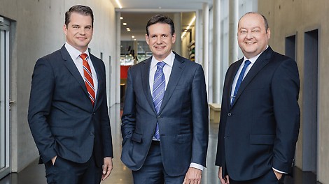
Best solving expertise in formwork and scaffolding
General information on our bauma appearance and the importance of bauma as an innovation platform; notes to the PERI project expertise and its presentation at bauma; information and news about PERI services and software solutions
02
Mar
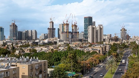
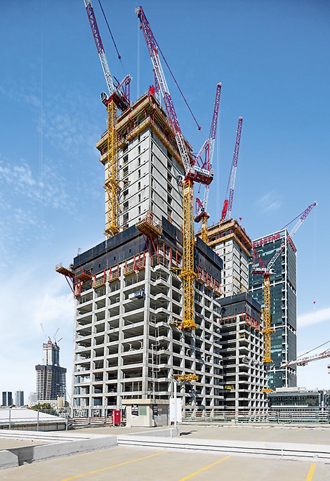
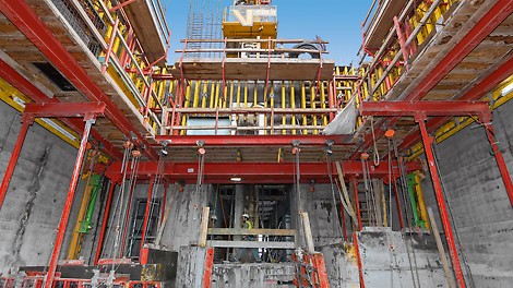
Climbing systems cost-effectively matched to one another
For a cost-effective execution solution, PERI´s Israeli engineers combined several climbing system variants. The system concept was perfectly matched with the climbing formwork and protection panels as well as exactly meeting construction site requirements.
11
Feb
Germany's best employers in 2016
German family-owned companies stand for long-term relationships, strong personalities and established products. PERI was named “Germany's best employers in 2016 – top 100” in a nationwide survey conducted by the news magazine Focus, which has now been published. PERI was voted number 7 in the group “Production and processing of materials and building materials, metals and paper” industry.
03
Feb
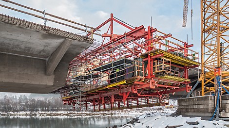
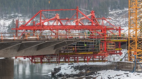
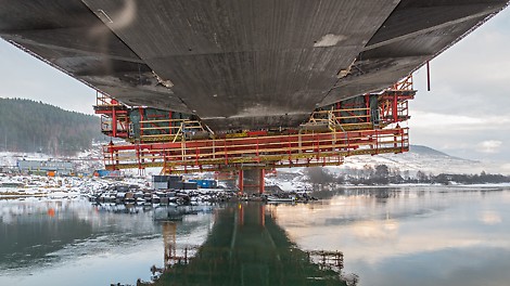
PERI balanced cantilever solution ensures optimized workloads
In the course of the European Route E6 expansion in Norway, the plans include a 320 m long bridge which spans the Gudbrandsdalen Lågen river. For the bridge superstructure, PERI civil engineering technology experts developed a balanced cantilevered solution based on the VARIOKIT Engineering Construction Kit.
25
Jan
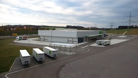
PERI expands its production capacities for scaffolding systems
The Weissenhorn-based company PERI has announced the purchase of the Silvergreen site in Günzburg. The new location will complement the main plant in Weissenhorn as the expansion possibilities there are very limited.
19
Jan

Best problem-solving expertise in formwork and scaffolding
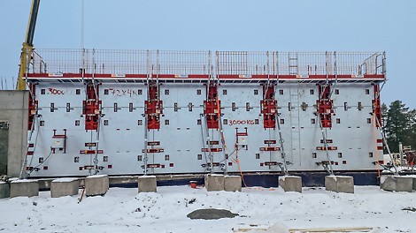
From 11th to 17th April 2016 in a 4,200 m² exhibition hall in the Open-Air Area North, PERI will be presenting the very latest formwork and scaffolding technology. The focus is on a range of innovations, practical system enhancements as well as further developments for different applications and target groups.
07
Jan
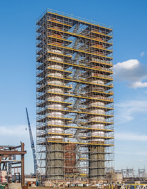
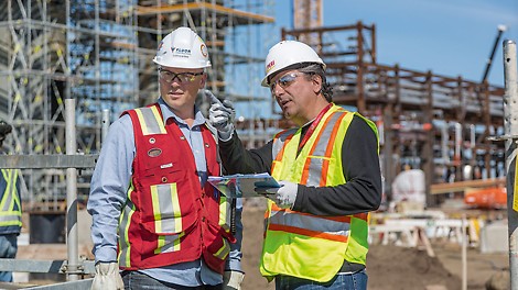
High level of safety and increased efficiency in industrial scaffolding
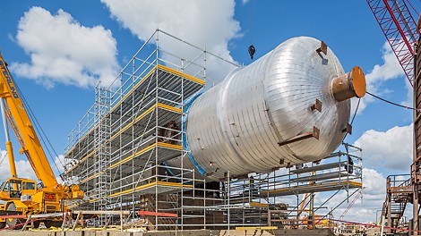
The PERI UP scaffolding system along with the integration of 3D scaffold planning at an early stage has reduced the time and cost factor while simultaneously increasing safety levels for the construction of an industrial plant in Canada.
09
Dec
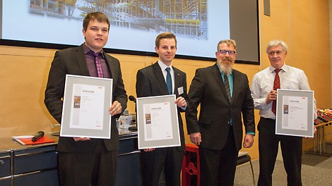
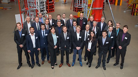
Expert jury determines winners of the 10th PERI student competition
Through participation in the Construction Exercise, PERI offers educational institutions providing construction-related courses not only the opportunity to gain valuable experience with a specific practical approach but also win attractive cash prizes.
02
Dec
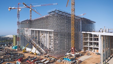
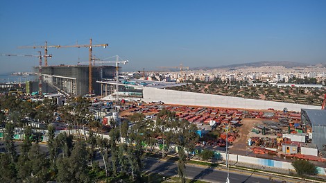
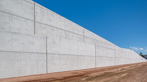
Earthquake-proof shoring solution for new iconic structure in Athens
Not far from the Faliro bay in Athens, the Stavros Niarchos Foundation Cultural Center (SNFCC) is being realized based on a design by star architect, Renzo Piano. PERI is supporting the construction of this extraordinary project with a comprehensive formwork and scaffolding solution which includes continuous on-site supervision along with a matching logistics concept for managing the enormous amount of materials.
18
Nov
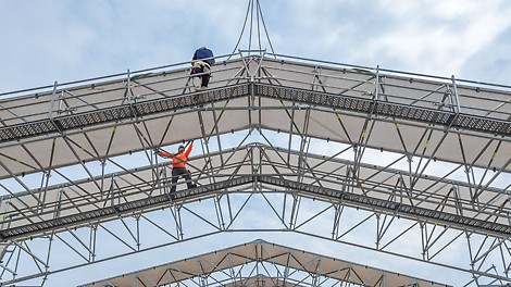
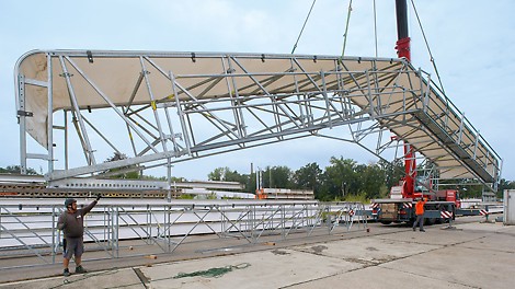
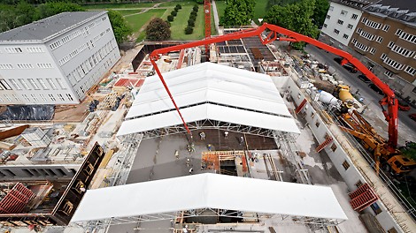
Safe access to weather protection roof – no PPE against falling required
For the LGS Weather Protection Roof from the extensive PERI product portfolio, a fast and reliable solution for safe working on roof girders is now also available: a walkway along the girder whereby the use of personal protective equipment against falling is no longer required.
18
Nov


Safe access to weather protection roof – no PPE against falling required
For the LGS Weather Protection Roof from the extensive PERI product portfolio, a fast and reliable solution for safe working on roof girders is now also available: a walkway along the girder whereby the use of personal protective equipment against falling is no longer required.
09
Nov
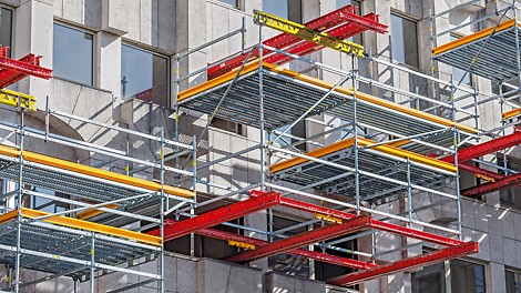
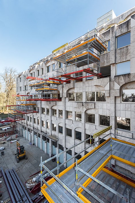
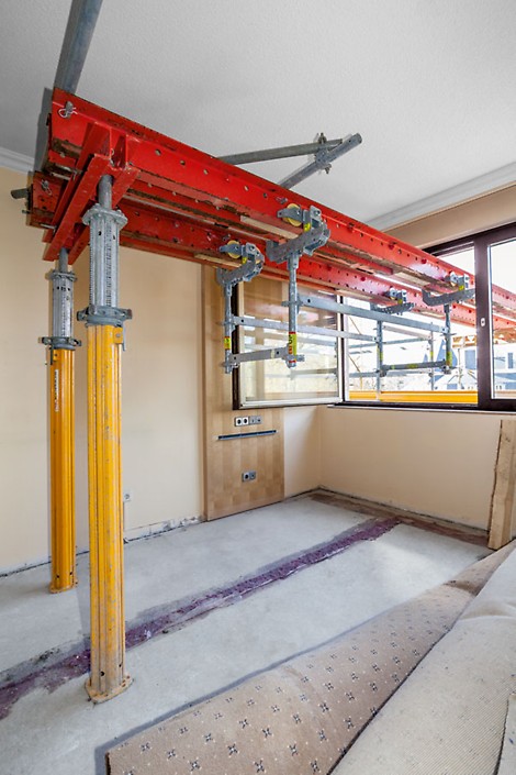
Cantilevered system combination for refurbishment measures
Cantilevered platforms have accelerated the complete renovation of a luxury hotel in Luxembourg. The customized project solution was based on two compatible PERI modular construction systems: VARIOKIT and PERI UP.
09
Nov


Cantilevered system combination for refurbishment measures
Cantilevered platforms have accelerated the complete renovation of a luxury hotel in Luxembourg. The customized project solution was based on two compatible PERI modular construction systems: VARIOKIT and PERI UP.
05
Oct
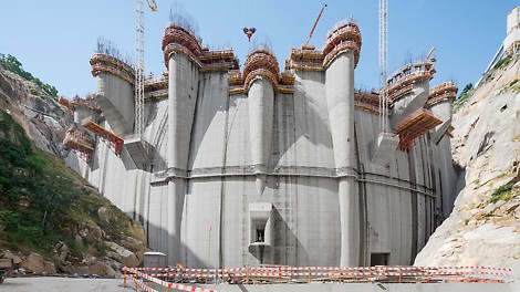
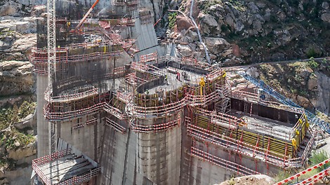
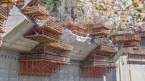
Elaborate engineering services for an imposing dam
PERI devised and supplied an optimised and safe formwork and scaffolding solution for construction of the Foz Tua Dam and the associated pumped-storage power station. The PERI specialists supported the construction firm, Barragem de Foz Tua, ACE, to ensure the build was completed on schedule and with precision, providing an elaborate concept, as well as logistical and technical services.
05
Oct


Elaborate engineering services for an imposing dam
PERI devised and supplied an optimised and safe formwork and scaffolding solution for construction of the Foz Tua Dam and the associated pumped-storage power station. The PERI specialists supported the construction firm, Barragem de Foz Tua, ACE, to ensure the build was completed on schedule and with precision, providing an elaborate concept, as well as logistical and technical services.
01
Sep
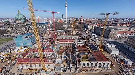


Formwork and scaffolding from one source for Berlin´s City Palace
For the reconstruction of Berlin´s City Palace, PERI supplied cost-effective formwork and scaffolding solutions from one source. In addition to providing large quantities of wall, column and slab formwork with fast shuttering and moving times as well as flexibly used scaffolding materials, the on-site support provided by the PERI engineers ensured that all requirements could be fulfilled along with maintaining the tight construction schedule.
11
Aug
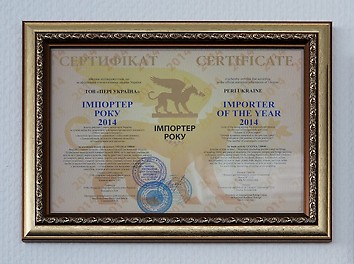
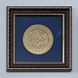
BEST SUPPLIER and IMPORTER OF THE YEAR Awards for PERI Ukraine
In recognition of its consistently high level of operational performance throughout 2014, PERI Ukraine has been presented with two awards: BEST SUPPLIER 2014 and IMPORTER OF THE YEAR 2014.
03
Aug
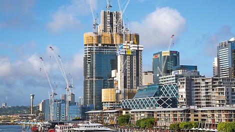
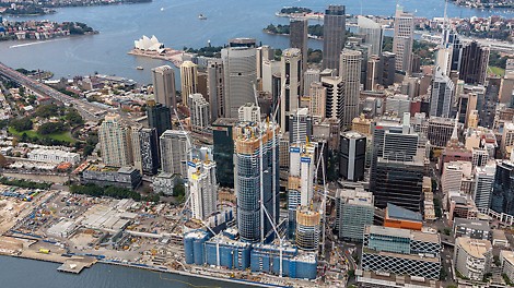
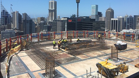
Construction time optimisation through comprehensive working safety and crane-independent climbing
The new LPS climbing protection panel from PERI provides comprehensive working safety and saves valuable crane time thanks to the mobile climbing hydraulics. This has accelerated construction progress on the International Towers Sydney complex on Australia's east coast.
14
Jul
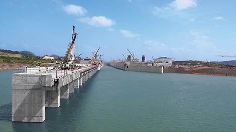
Completion now within reach: flooding of a canal section
With the flooding of a canal section in June 2015, tests have begun in readiness for the scheduled opening of the expansion project in 10 months time. Since 2011, PERI has delivered around 1,100 containers of formwork and scaffolding materials to Panama. Once again, the company has demonstrated its superb service capabilities as well as ability to deliver – in this particular case through the excellent teamwork of several subsidiaries.
06
Jul
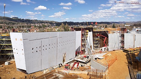
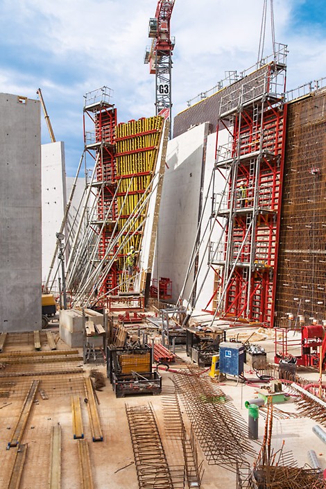
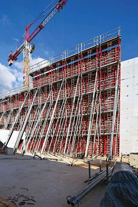
Replica of a cave from the Paleolithic Age realised in the original form with PERI
The museum complex is dedicated to showcasing cave paintings with the central feature being a complete replica of the "Lascaux 4" cave. PERI has supported the project by providing an overall concept comprised of detailed technical preparation, absolute safe formwork solution and continuous consultation.
16
Jun
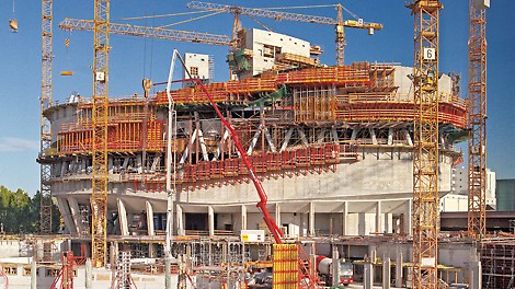
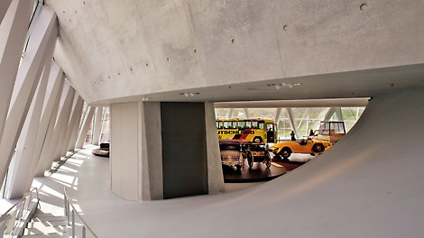
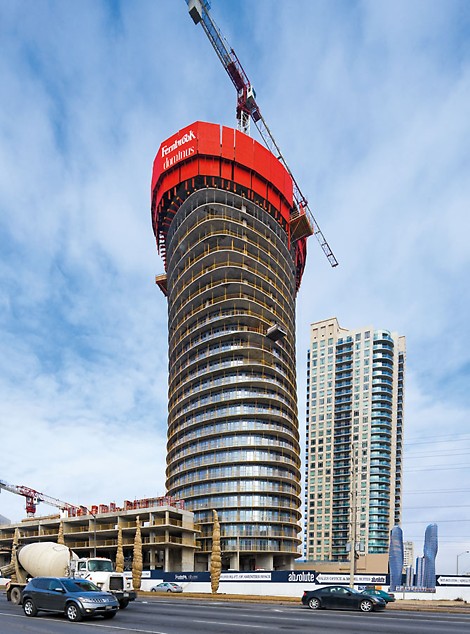
Formwork in every shape and dimension – even faster with the new CNC system
PERI is keeping pace with this trend: with individual formwork solutions, the formwork and scaffold expert ensures that complicated designs become reality. In order to increase the required capacity at the Weissenhorn formwork assembly plant, a second state-of-the-art CNC timber processing facility started operations in the spring of 2014.
16
Jun
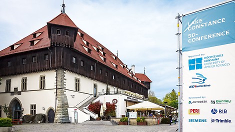


PERI accompanies the construction sector for Industry 4.0 integration
PERI and other companies in the construction industry are becoming increasingly involved with the issue of "Building Information Modelling" (BIM), the all-embracing project planning in five dimensions. At the third 5D conference in Konstanz, Germany, the trend towards BIM was adopted and welcomed as the new standard.
01
Jun
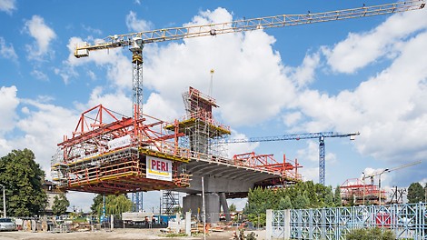
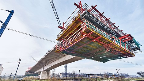
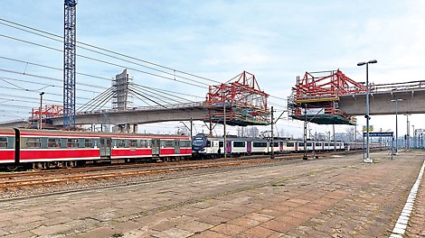
Cost-effective cable stay bridge construction with VARIOKIT balanced cantilever equipment
The current expansion of the Krakow metropolitan railway network (KST) requires, among other things, crossing of the Krakow-Plaszow railway junction. Ensuring that daily rail operations remained unaffected during the construction of the 252 m long crossing was a prerequisite which meant the general contractor decided in favour of the cantilevered construction method for realizing the extradosed bridge with its hollow box cross-section.
05
May
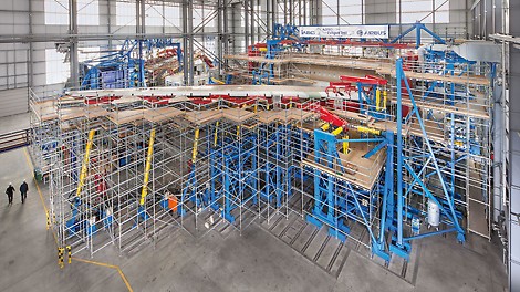
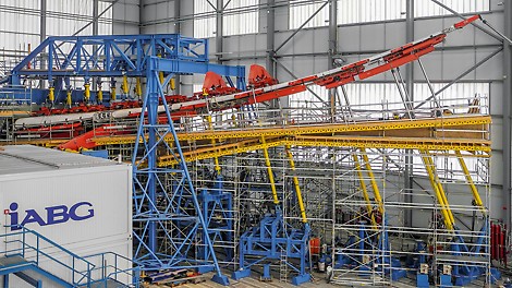
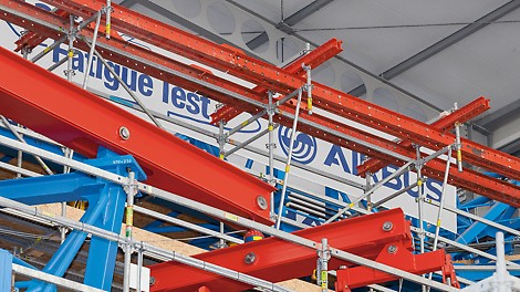
Modular, combinable, adaptable: Testing for Take-Off with PERI UP
As an essential prerequisite for the approval of the Airbus A350 XWB, the IABG Industrieanlagen-Betriebsgesellschaft mbH has carried out an extensive range of tests on the new wide-bodied aircraft at its testing facility in Erding. With the scaffolding solution from PERI, optimal adaptation of the working levels for the fuselage and wings was achieved.
16
Apr
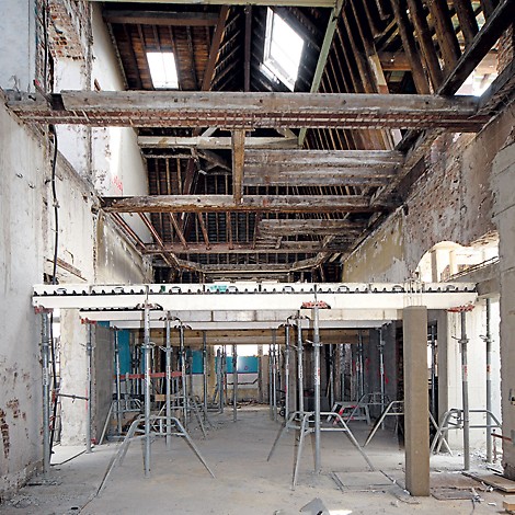


Competent handling of renovation work with project-specific solutions
Construction work on existing buildings frequently places high demands on clients, planners and building contractors. The entire planning procedure as well as the equipment to be used must be adapted to match the project-specific characteristics of the structure and, in particular, the constructional environment. With a wide range of products and their sophisticated use, PERI succeeds in finding the most suitable and cost-effective solution for each of the upcoming tasks.
01
Apr
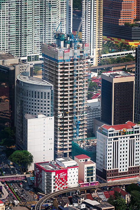
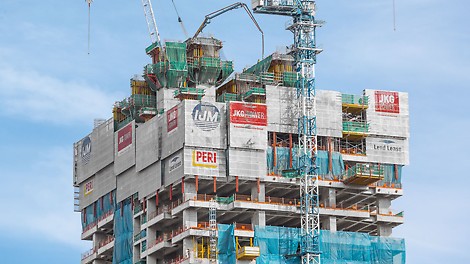
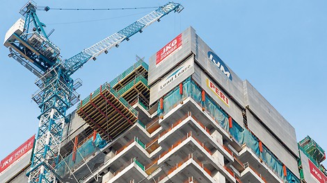
Working faster due to safer conditions
For the construction of the JKG Tower high-rise building complex – consisting of a 32-storey office tower along with a 13-storey parking facility – safety has been given the highest priority. As a result, the PERI formwork and shoring solution has also included, among other things, a corresponding training programme for the construction team.
25
Mar
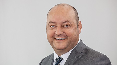
Leonhard Braig appointed Managing Director at PERI
Weissenhorn, 25 March 2015. Leonhard Braig (46) has been named Head of Products & Technology at PERI GmbH effective as of mid-April 2015. He will be responsible for the areas of product management, product technology, development, procurement, production and logistics.
03
Mar
Tunnel formwork with record-breaking dimensions
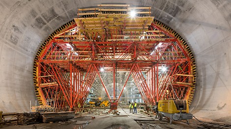
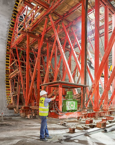
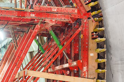
With a length of 144 m and a width approaching 23 m, the "Place de Martyrs" metro station boasts some very impressive dimensions. In addition, the entire 1.7 km long extension of the Algiers metro system runs under historic ground. For this project, an international team of PERI engineers designed economically optimized tunnel formwork solutions, tailored to meet the varying requirements.
03
Feb
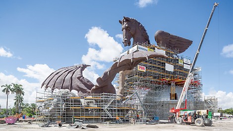
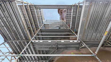
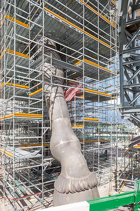
Super-sized bronze casting: 3D-puzzle on PERI UP scaffolding
For the erection of the extraordinary Pegasus bronze sculpture in Miami/Florida, PERI UP Rosett Flex provided optimal working conditions. The modular scaffold system proved once again just how flexible and versatile it is, adapting to the complex geometry in 25 cm increments.
20
Jan
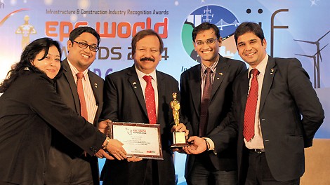
PERI India won the EPC World Media, Ernst & Young and Zee Business Group Award 2014
PERI India has been honoured with the EPC World, Ernst & Young and Zee Business Group Awards 2014 being an “Outstanding Company in Formwork and Scaffolding Sector”. The award was handed over on 18th of December 2014 in New Delhi.
01
Jan
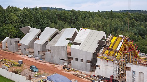
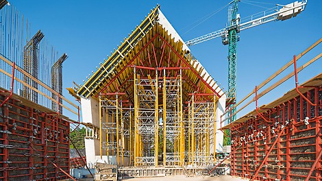
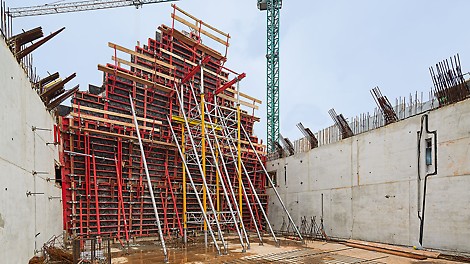
Complex architecture primarily achieved with system formwork
In Poland, the mausoleum commemorating a mass murder of the entire village of Michniów and other Polish villages across the occupied country during the World War 2 is currently being constructed. The museum features a traditional village hut which gradually falls apart. Numerous offsets and inclined surfaces characterize the structure as well as the distinctive timber-like finish on concrete surfaces.
02
Dec
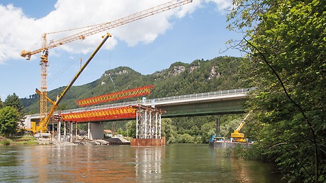
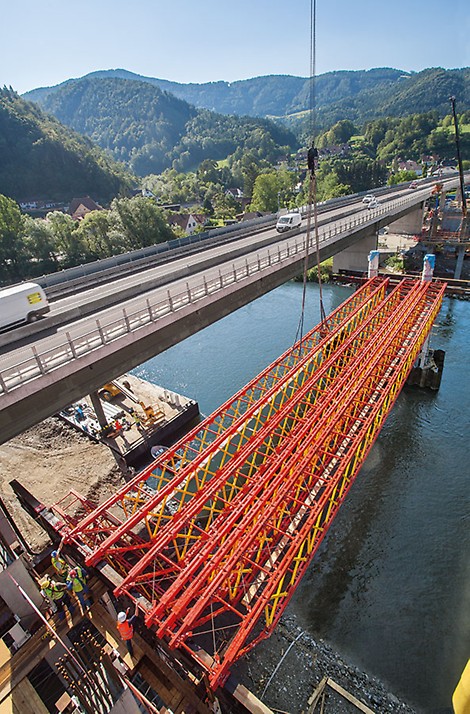
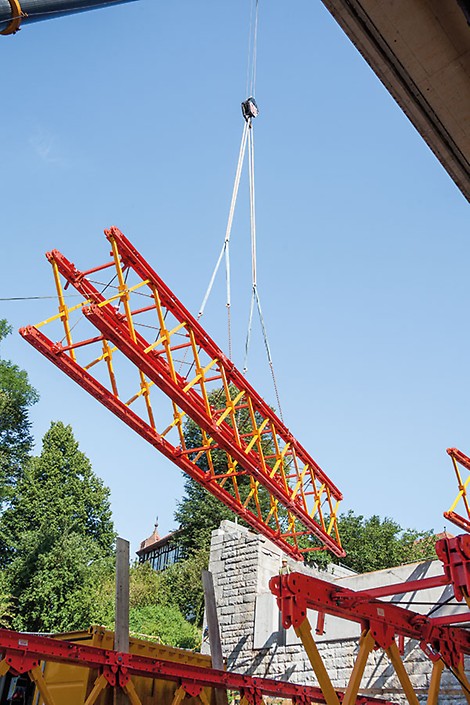
Large-spanned trusses with high load-bearing capacity and low deadweight
For construction of the Mur Bridge, the new PERI VARIOKIT lattice girder system is being used for the first time in Austria. This is characterized by its extremely high load-bearing capacity with a comparably low weight; in addition, the system components can be quickly installed and have a very flexible use.
10
Nov
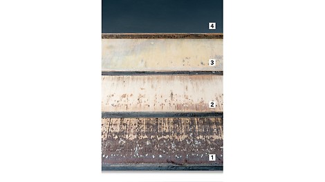
Full-face surface repair for PERI Pave production pallets
After successful tests had been carried out with PERI Pave recently, PERI decided to cooperate closely with PyraTec in future: as a result, the specialist company will now take on the sustainable renovation of PERI production pallets with immediate effect – whilst taking into account the high PERI quality standards.
04
Nov
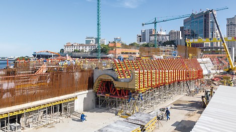
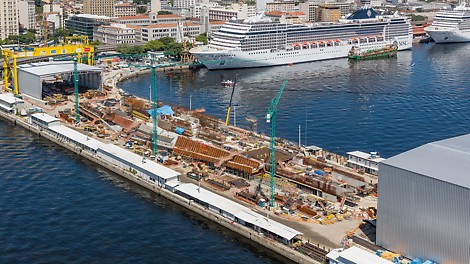
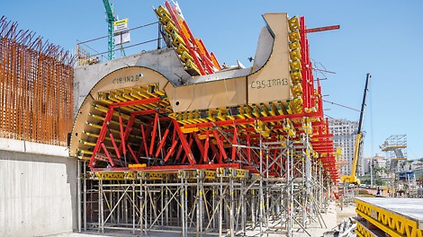
Trend-setting forming
A customized PERI formwork and scaffolding solution with 3,500 project-specific special formwork elements ensured that the realization of an extraordinary museum was carried out within the specified time-frame and budget.
01
Oct
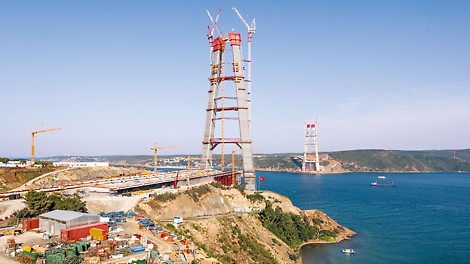
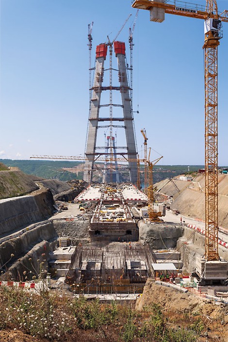
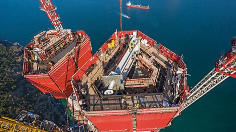
Highest concrete bridge pier in the world with PERI ACS self-climbing formwork
In the north of the Turkish metropolis, the third and largest bridge is currently being built across the Bosphorus. The suspension bridge is supported by two A-shaped pylons and reaches a height of around 330 m thus making it one of the highest in the world. The construction of the upper area of the two piers is being carried out in 21 concreting sections, each 4.60 m.
11
Sep
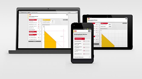
PERI Apps make construction site operations easier
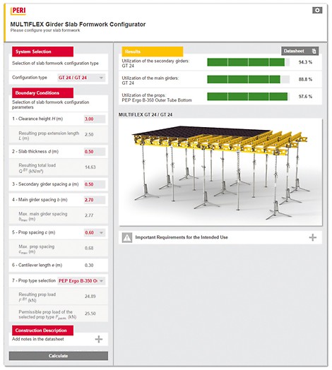
PERI has developed resp. updated three of its helpful apps for formwork and scaffolding: Formwork Load Calculator, MULTIFLEX Configurator and ST 100 Stacking Tower Configurator are now available on the website featuring an extensive range of benefits.
01
Sep
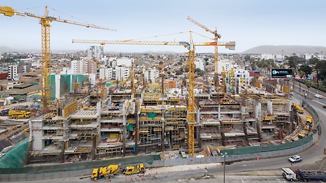
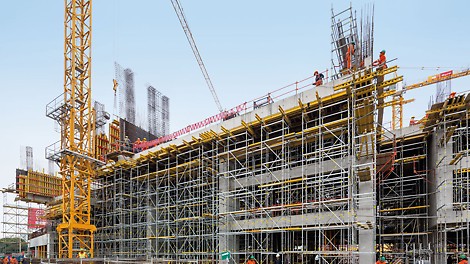
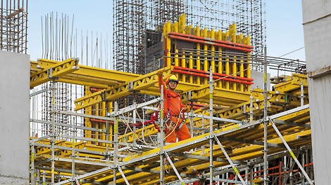
Grandstand-style campus realized in a short construction period
With the help of a customized PERI formwork and scaffolding solution, a new university campus is being constructed in the capital of the South American country of Peru – complete with high architectural requirements as well as having to maintain a short construction period.
01
Aug
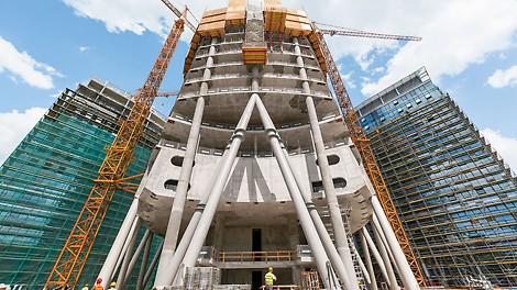
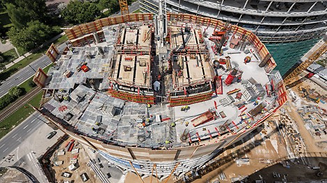
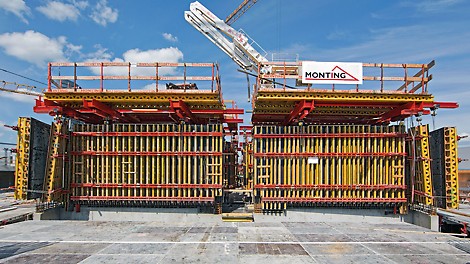
Quickly and safely to the top with optimally adapted climbing technology
In Warsaw, the Warsaw Spire office complex is currently being constructed. The 220 m high, waist‑like office tower complete with elliptical ground plan characterizes the appearance of the building ensemble; the tower is flanked by a 55 m high building on each side. PERI has planned and supplied the complete formwork and scaffolding solution for the complex.
01
Jul
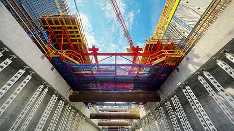
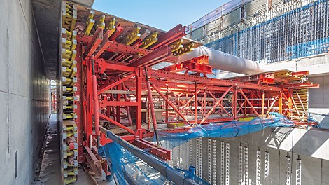
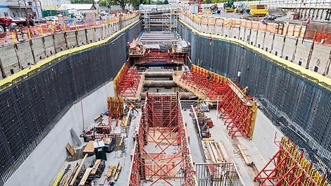
System-based project solution saves time and money
The formwork and scaffolding solution provided for the construction of the new subway station in Seattle was the result of competent engineering and a project-specific construction kit system. In addition to the widest possible use of rentable PERI system components, the optimized construction method in particular ensured significant time and cost savings.
30
Jun
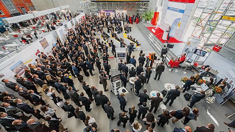


Family businesses offer international career opportunities
By arranging the Family Business Career Day we want, therefore, to inform candidates about the opportunities in our company and especially about potential positions around the world.
03
Jun
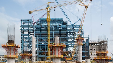
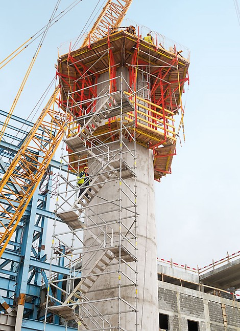
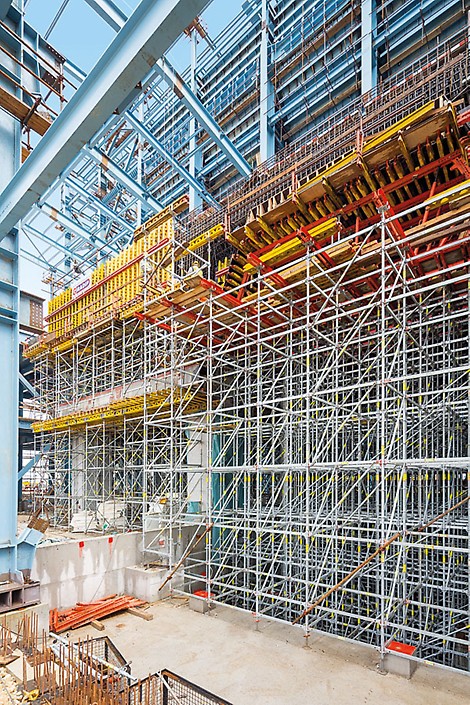
Test of strength for PERI formwork and scaffolding
The Energy Financing Team (EFT) is currently constructing the Stanari coal powered power plant near Doboj. PERI supplies two of the building contractors involved with a customized formwork and scaffolding solution. In addition to the materials, it is the technical preparation done by PERI engineers that provides extremely helpful support thus ensuring efficient project execution.
05
May
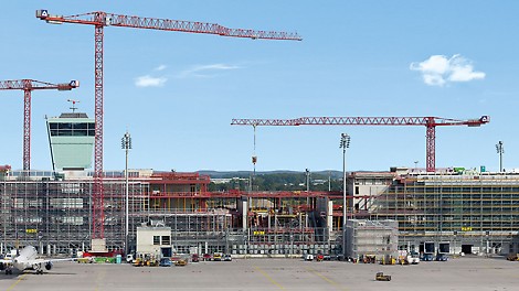
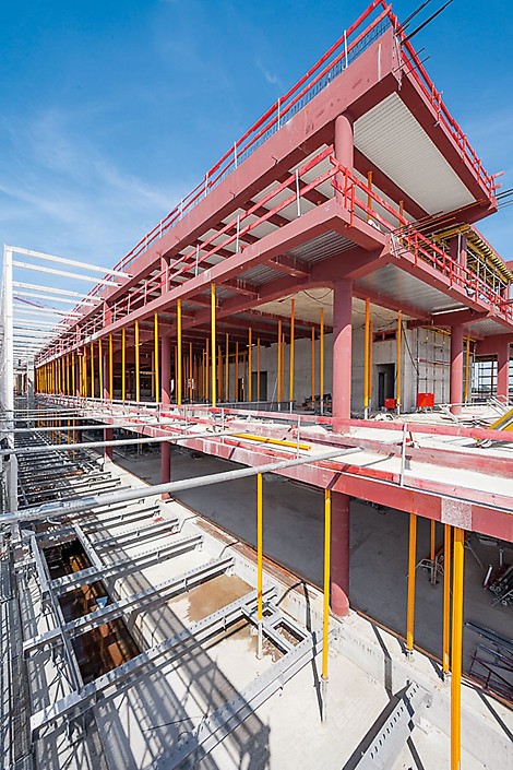
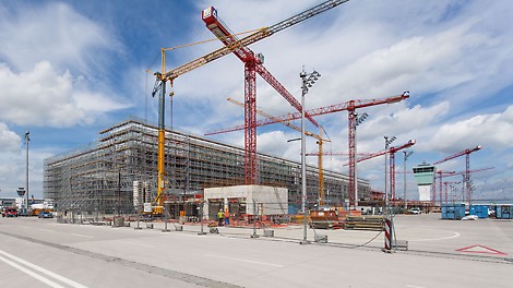
Comprehensive range of services for construction and scaffolding companies
In order to be able to handle around 11 million additional passengers per year from 2015 onwards, Terminal 2 at Munich Airport is currently being expanded in the form of a satellite terminal. PERI has supplied a complete solution consisting of formwork, scaffolding and engineering – and convinced both the construction company and the scaffolding contractor with its safer and faster system technology as well as a customized package of services.
28
Apr
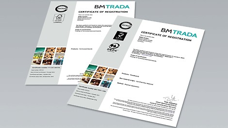
Seal of approval: Recognizing an ecological manufacturer
A positive example for ecological and sustainable developments is the formwork and scaffolding manufacturer PERI, whose material for its plywood sheets originates from sustainable forests. The forest areas where the raw materials come from are reforested after every harvest – this is verified through the PEFC and FSC certifications.
22
Apr
World Wide Success: myPERI wins award in Great Britain
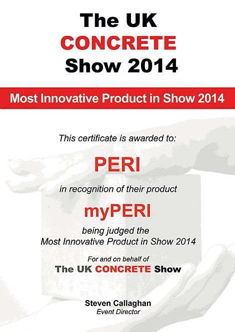
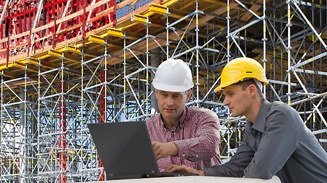
Keeping an eye on all information concerning formwork and scaffolding materials on construction sites around the clock – this is something that has been available in Germany since February 2012 with myPERI. After successfully completing a series of test runs, the English version has been integrated into the range of services offered by the PERI subsidiary, and promptly received the award for "Most Innovative Product in Show" at the UK CONCRETE Show.
03
Apr
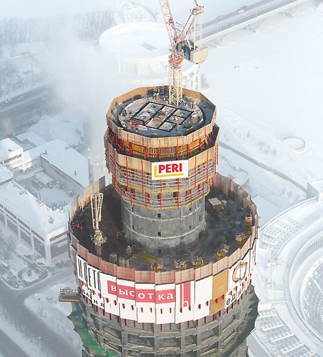
Project-specific climbing solution with practical adaptation
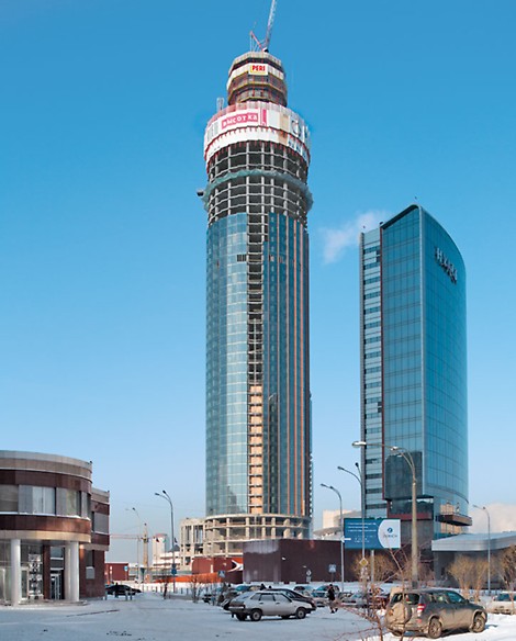
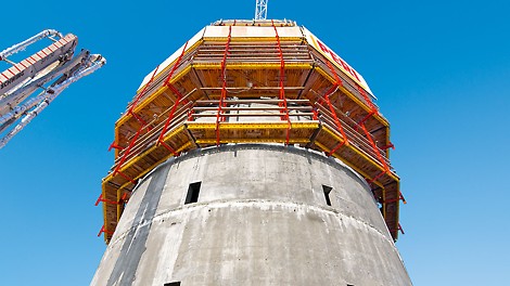
A customized PERI climbing formwork solution has been supporting the rapid construction progress on the ISET Tower in Yekaterinburg. The formwork concept has taken into account the high wind loads as well as the variable number of elevator shafts with varying dimensions.
01
Apr

Fabian Kracht new managing director at PERI
From April 1, 2014 on, Dr. Fabian Kracht (35) will be the new managing director for Finance and Organization at PERI GmbH, one of the global market leaders for formwork and scaffolding.
03
Mar
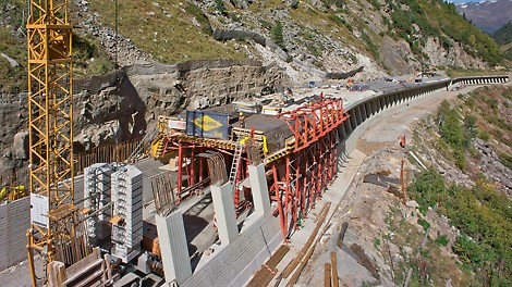
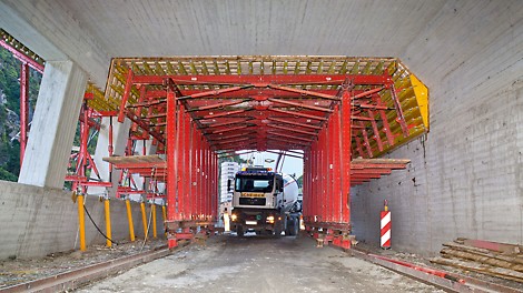
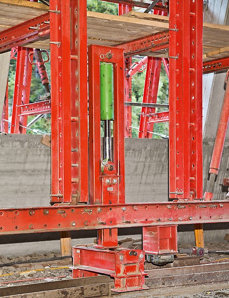
Customized tunnel formwork carriage allows both construction and utilization
A VARIOKIT tunnel formwork solution accelerated construction progress for the 228 m long Marchlehner gallery, situated at a height of 1,800 m above sea level. The competent planning took into account all possible project requirements which ensured on-schedule completion before the onset of winter.
05
Feb
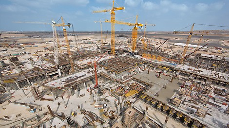
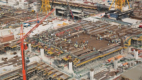
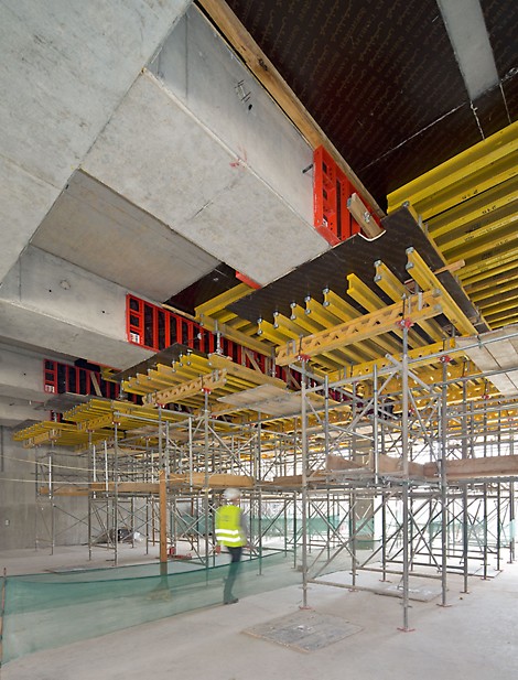
Over 6,000 slab tables in continuous use at the Midfield Terminal project
PERI has provided yet another convincing performance with the construction of the Midfield Terminal at Abu Dhabi International Airport with the delivery of enormous amounts of materials at short notice as well as competent engineering for the related formwork and scaffolding planning.
07
Jan
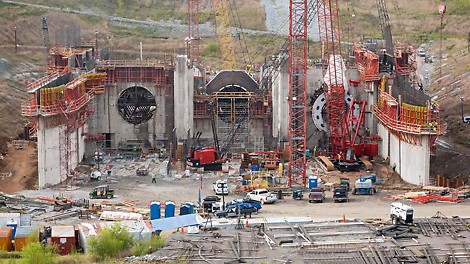
From the planning to implementation – comprehensive engineering services for construction of the power plant shell
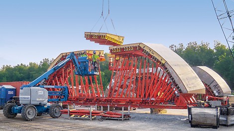
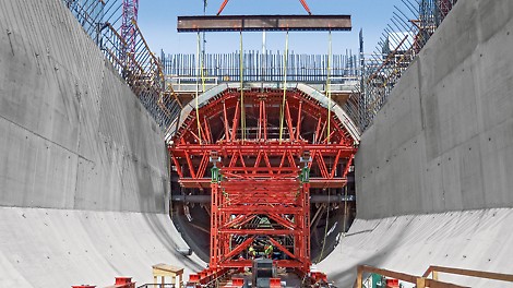
For the Smithland hydropower station, PERI provides a customized formwork and shoring solution. The extremely tight construction schedule, massive structural elements and in part multi-curved surfaces required a huge number of specially-made 3D formwork units in addition to large quantities of system equipment.
05
Dec

Documented efficiency: shuttering times reduced by 50 % with Maximo
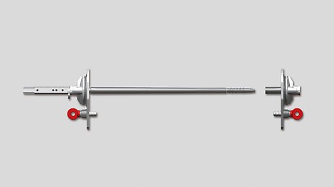
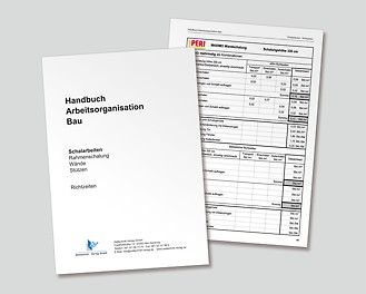
The reference times featured in the "Arbeitsorganisation Bau" handbook are a valuable basis for construction site calculations in Germany. With Maximo, the latest edition on panel formwork contains for the first time a system with one-sided tie technology – which has been proven to save up to 50 % on workload.
02
Dec
Formwork solution for pylons and bridge superstructure from one source
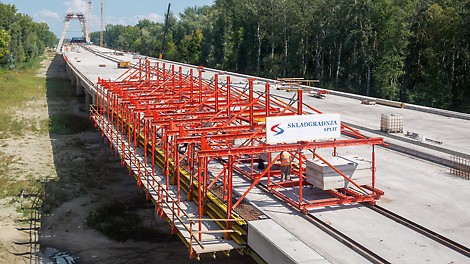
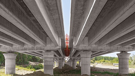
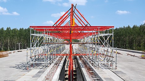
The bridge over the Drava river is part of the realization of the 90 km long A5 motorway development in eastern Croatia. Peri planned and delivered not only a cost-effective climbing formwork solution for the construction of the up to 75 m high bridge pylons, but also the concept for the creation of the piers and the parapet solution for the foreshore bridges.
25
Nov
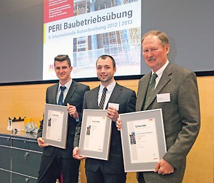
International competition with high requirements and a long tradition
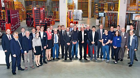
For the tenth time, Peri is offering all educational and training institutions involved in the field of construction the opportunity of participating in its well known Construction Exercise. The competition not only provides valuable experience with a specific practical application but also the chance to win attractive cash prizes. Winners of the 9th competition were recently awarded – and thoughts have already turned to the next competition.
04
Nov
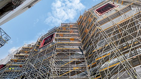
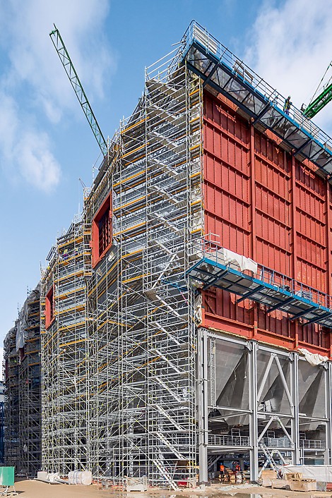
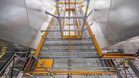
High level of working safety for scaffold assembly and use
As part of the planned construction of the new power plant, the Peri Up Rosett Flex has proved to be extremely adaptable during the assembly phase – in so doing, it has fulfilled the highest requirements regarding the installation of the working platforms. The fact that the modular scaffolding can be assembled with the guardrail in advance means that the safety level required during scaffold erection is already guaranteed to a high degree.
10
Oct
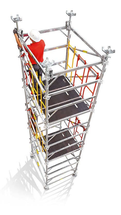
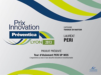
Recognized as an outstanding innovation: the Peri Up Shoring Tower MDS
At the Préventica in Lyon – a trade fair which focuses on all aspects relating to occupational safety – a jury awarded the Peri Up Shoring Tower MDS the innovation prize in the category "Working at Heights". The shoring tower is characterized by the fact that a totally safe erection procedure is fully integrated throughout.
01
Oct
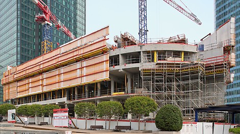
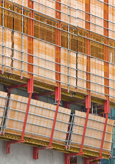
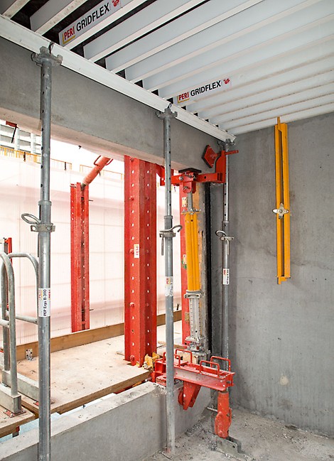
Made-to-measure climbing formwork solution – all-round enclosure and formwork scaffold
For the Hotel Mélia in the "La Defense" office district just outside Paris, Peri has developed a climbing formwork solution that not only provides complete enclosure of the structure but also serves as erection support for the precast parapets.
13
Sep
Group Management at PERI will be extended
PERI, global market leader for formwork and scaffolding with a turnover of 1.052 billion Euros in 2012 and 6,600 employees worldwide, is going to extend its Group Management.
02
Sep
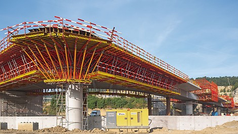
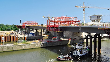
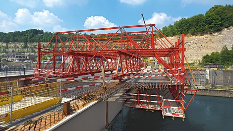
Individual project solution with construction kit system
The Variokit modular construction system is being used for the cost-effective realization of the steel composite bridge over the extended Lanaye lock facility in Belgium. Based on standardized, rentable system components, Belgian and German PERI engineers adapted the bridge solution to match the range of construction site requirements.
05
Aug
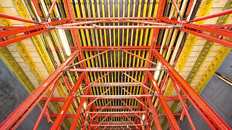
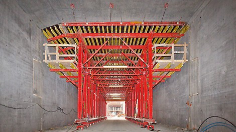
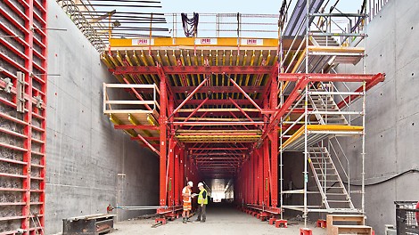
Customized formwork and scaffolding solution from one source
Around 620 m of the extensive Nordhavnsvej infrastructure project runs underground. The twin-tubed, rectangular tunnel is being realized using the cut-and-cover method – the walls with Trio panelized formwork in advance followed by the slab formed with the Variokit tunnel formwork carriage. With the customized project solution, the construction team has achieved a three week cycle for the 25 m long concreting sections.
01
Jul
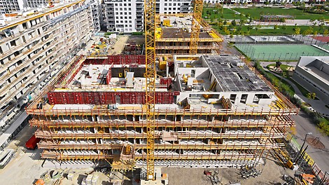
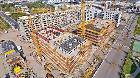
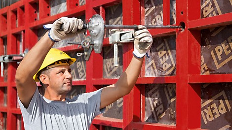
Construction time savings with MAXIMO and SKYDECK
On the former North Station area, the "Schwarzatal" non-profit real estate developer is currently realizing a very special housing project. The use of modern and efficient formwork systems for the walls and slabs ensured that the very tight completion deadline of only 10 months for the building shell could be met.
07
Jun

Digital solutions with added value
At bauma 2013, PERI presented a number of new digital innovations which included the launch of the PERI handbook as an application for mobile devices. In addition, the company unveiled applications for determining the concreting speed as well as a configurator for the MULTIFLEX slab formwork designed for use on smart phones and tablets.
05
Jun
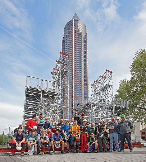
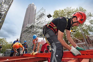
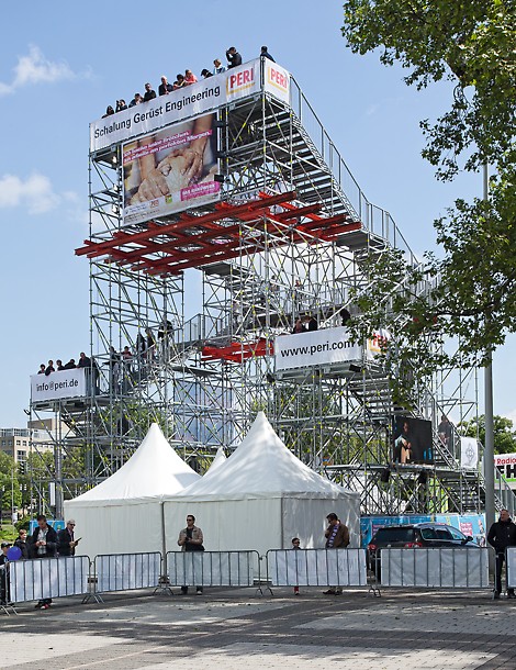
A hugely impressive appearance - PERI UP at the Skyscraper Festival
In May 2013, the fifth Skyscraper Festival in Frankfurt am Main took place. 18 high-rise buildings opened their doors to the general public and countless other programme highlights thrilled and entertained more than a million visitors.
03
Jun
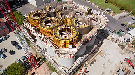
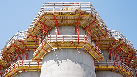
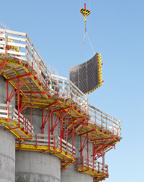
High quality in continuous 2-week cycles
Using a PERI climbing formwork solution precisely tailored to meet the project requirements and reduced material requirements, nine silos grew steadily upwards in regular 2-week cycles. Ready-to-use elements supplied directly from the PERI formwork assembly hall ensured dimensional stability.
03
May
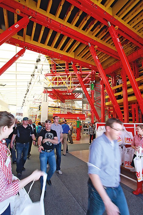


Increased profitability for VARIOKIT tunnel formwork carriage
At this year's bauma, PERI presented new system components and a wide range of further developments for formwork and scaffolding technology. Also the tunnel formwork carriage exhibited at the fair is characterized by detail improvements that have been designed to increase the cost-effectiveness and accelerate the assembly.
03
May
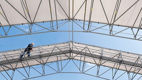

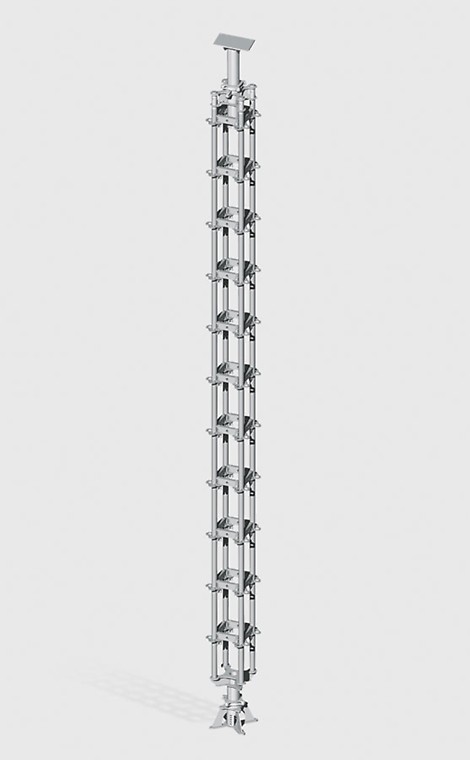
Innovative technology, comprehensive solutions and customer-oriented presentations
The complete range of scaffolding applications was presented along with new system components and numerous further developments. The exhibition offered prospective customers the best opportunity to learn more about the proven and innovative technology as well as PERI services in greater detail. The entire week of the fair in Munich was characterized by an extremely positive feedback from the industry.
02
May

Impressive performance with extremely positive feedback at the world´s biggest fair
More than 530,000 visitors from over 200 countries attended bauma 2013. Every third visitor to the fair visited the purpose-built PERI exhibition hall which was located on the Open-Air Area North. On over 4,000 square metres, the Weissenhorn-based company presented proven formwork and scaffolding systems as well as numerous innovations.
23
Apr
Innovative technology, comprehensive solutions and customer-oriented presentations at bauma 2013
At this year´s bauma, PERI presented a number of new formwork and scaffolding systems as well as a wide range of further developments. On an area of over 4,000 m², the exhibition offered visitors the opportunity to learn more about proven and innovative technology at first hand.
15
Apr
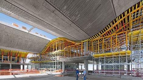
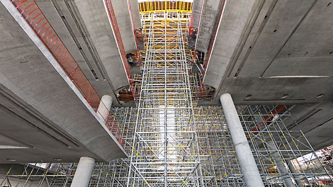
Undulating roof construction efficiently formed
An undulating roof structure is being formed by means of longitudinally movable slab tables at a height of 20 m. The project solution developed by PERI´s Argentine engineers fulfils the high architectural concrete requirements as well as maintaining the short construction period from an economic point of view.
04
Mar
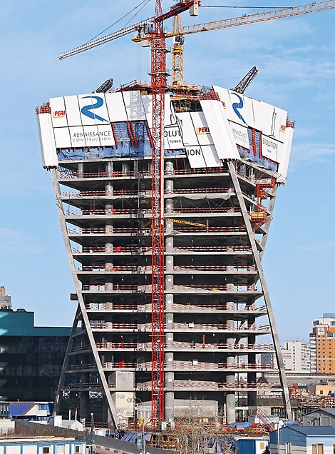
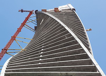
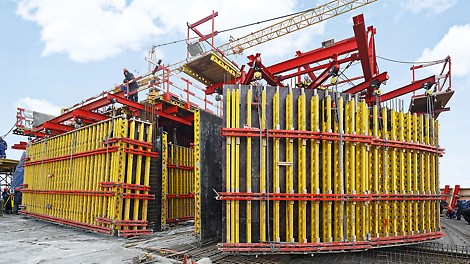
Twisted floors in weekly cycles
Every week, Moscow´s new landmark is gaining 4.30 m in height – with each completed floor twisted 3° in relation to the preceding one. For this, PERI engineers developed a crane-independent formwork concept on the basis of the RCS and ACS self-climbing technology.
04
Feb
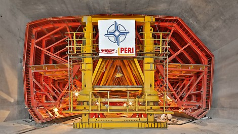
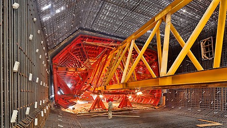
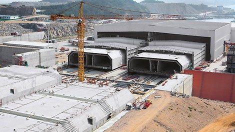
Incremental launching forming machine for the world´s longest underwater tunnel
With the help of PERI know-how, the longest underwater tunnel in the world is currently under construction in China. Two hydraulically-operated shuttering machines are being used for the efficient realization of 33 tunnel elements by means of the incremental launching method. Each standard element is an incredible 180 m long and weighs over 70,000 t.
16
Jan
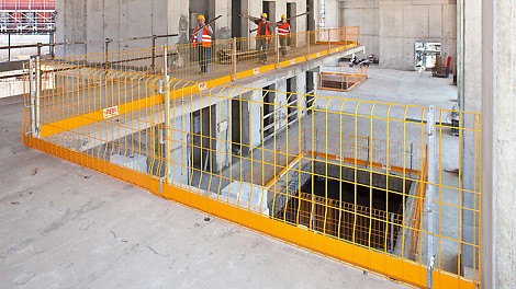


Construction-compliant accessories for the PROKIT safety system
For the PROKIT EP 110 safety system, additional system components are now available: a pallet which greatly facilitates logistics operations for the side mesh barrier as well as a plastic screw-on sleeve that is used for easy mounting of the slab feet.
16
Jan


Construction-compliant accessories for the PROKIT safety system
For the PROKIT EP 110 safety system, additional system components are now available: a pallet which greatly facilitates logistics operations for the side mesh barrier as well as a plastic screw-on sleeve that is used for easy mounting of the slab feet.
07
Jan
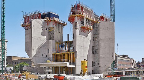


Perfectly combined systems: safety and quality during the entire construction
Ideally combined systems form the basis for efficient and cost-effective construction work. With this very much in mind, PERI engineers tailored their formwork and scaffolding solution to precisely match the project requirements for the construction of the sculpture-like "CaixaForum".BE THE FIRST TO KNOW
Subscribe to PERI Malaysia newsletter to be the first to see inspiring content, news, and exclusive offers for your projects.